Calibrating
Overview
Calibration is the process of setting an accurate scale on a drawing so that measurements taken within the system reflect real-world dimensions. It ensures that all quantities, distances, and areas calculated from the drawing are reliable.
Without calibration, any measurement taken from a drawing may be inaccurate due to scaling differences between the original file and its displayed version.
Calibration should be performed when:
- A drawing is first uploaded into the system
- The drawing scale is unknown or unreliable
- Measurements appear inconsistent with known dimensions
- The drawing has been resized, rotated, or converted
Calibration Workflow
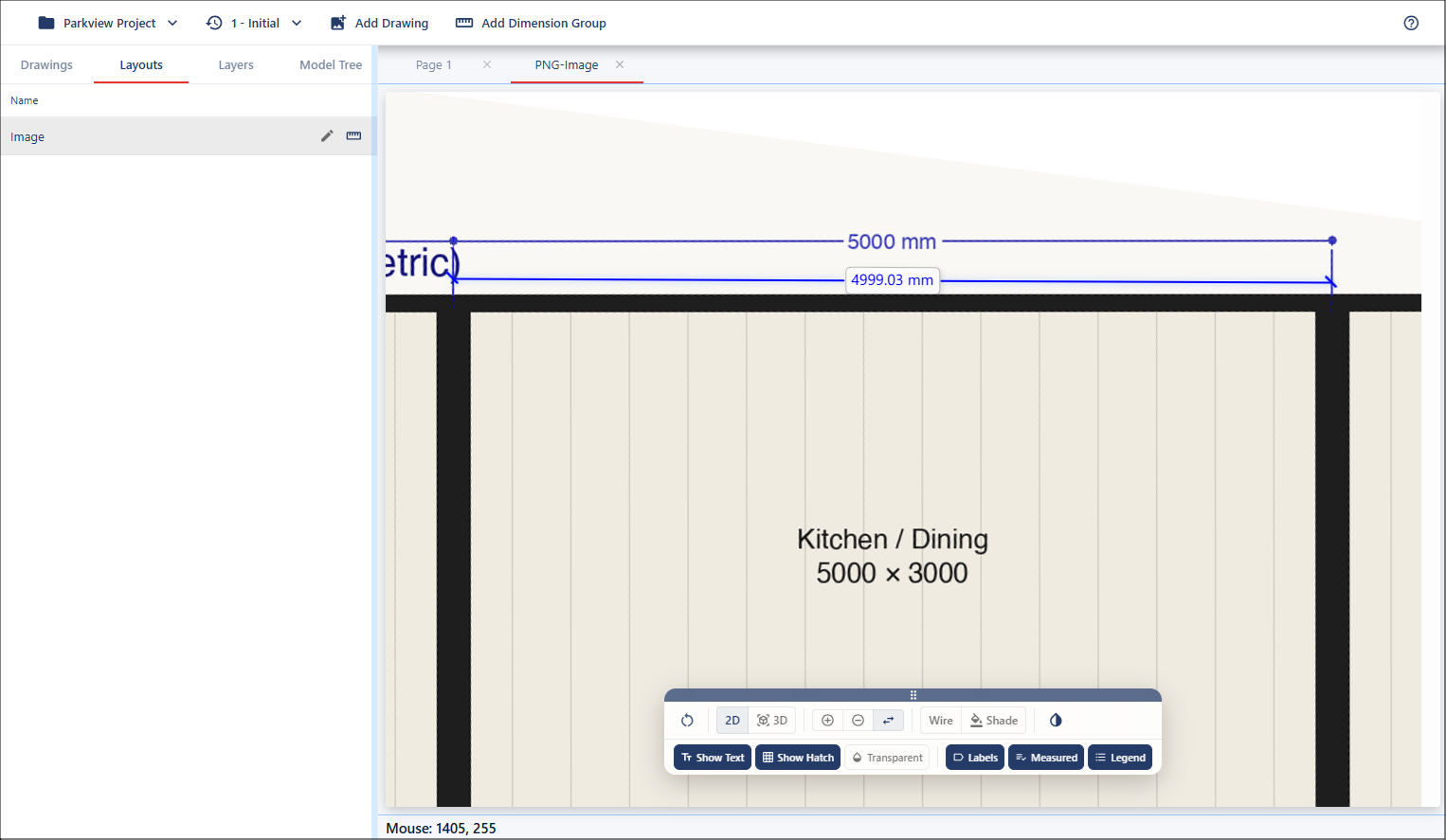
For calibration, you need to focus on a known dimension within the drawing. This could be a common reference, such as a door, but in this example, we'll use a known dimension line provided in the drawing.
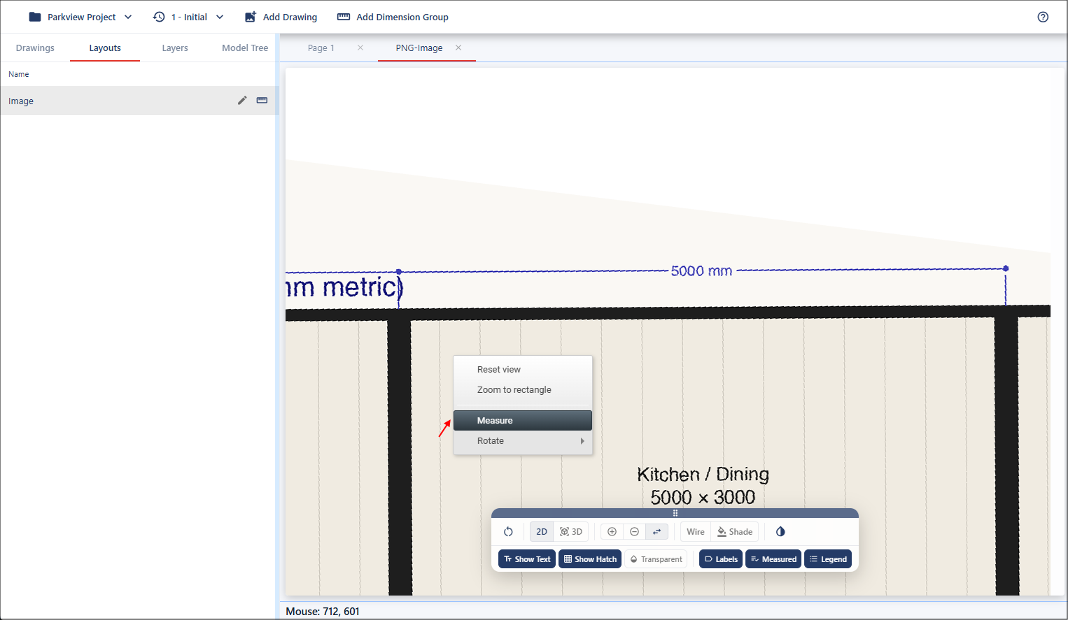
Start by zooming in on the dimension. There is no snap functionality when working with a drawing that has no geometry applied. Open the Measure tool by right-clicking in the viewport and selecting Measure.
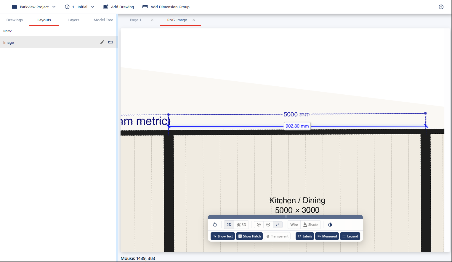
Left-click at the starting point and drag your mouse to the endpoint. The drawing is not to scale.
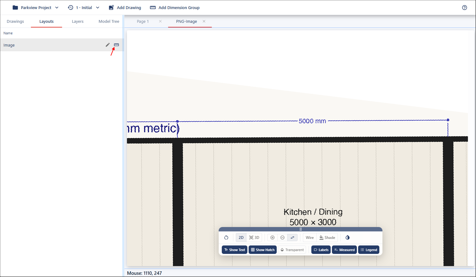
Click the Start Calibration button for the layout you are working with to open the Calibration Properties dialog.
This dialog can be easily moved around the viewport, left-click on the dialog header to move the dialog to a position that is not in your way. To activate the measurement mode, click Calculate for the X Factor field.

Move to the starting point of the dimension, then left-click and hold while dragging along the measurement.
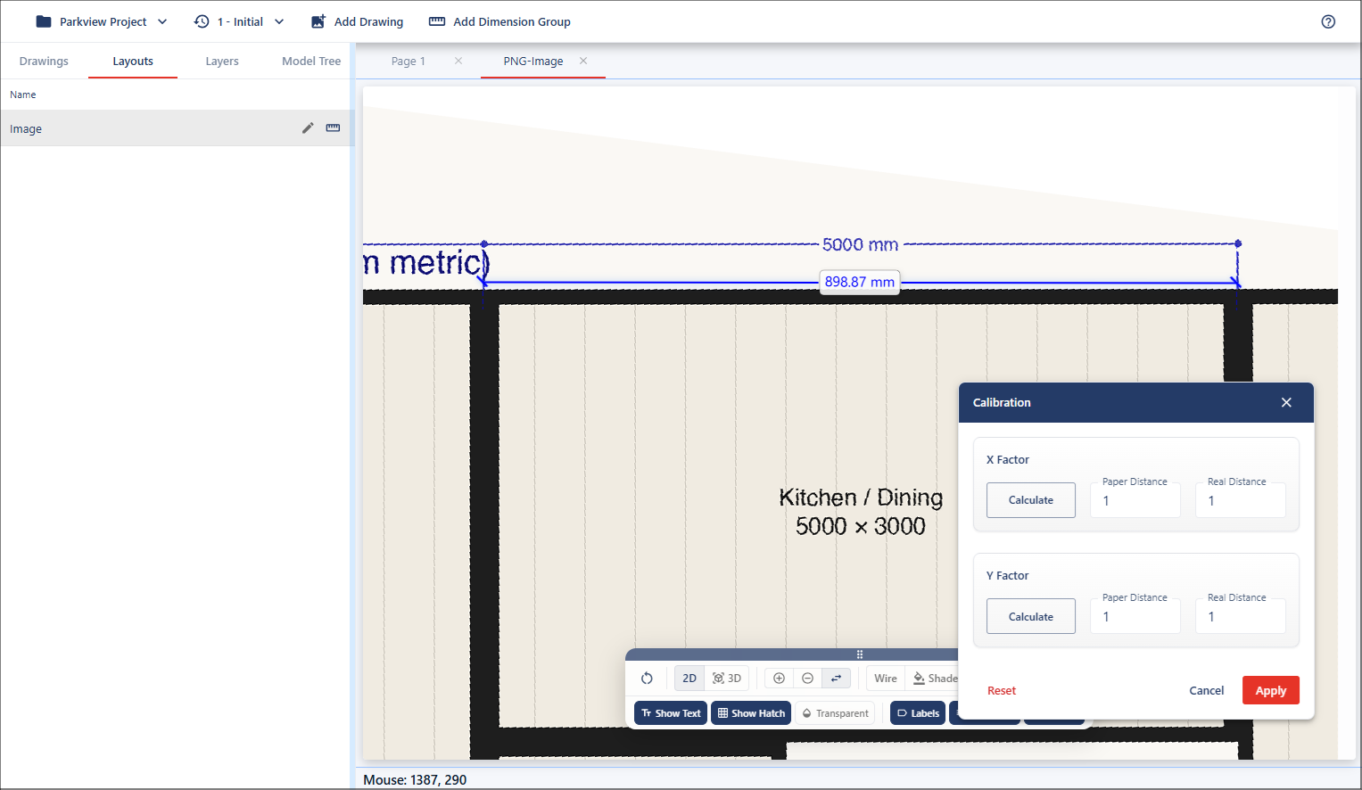
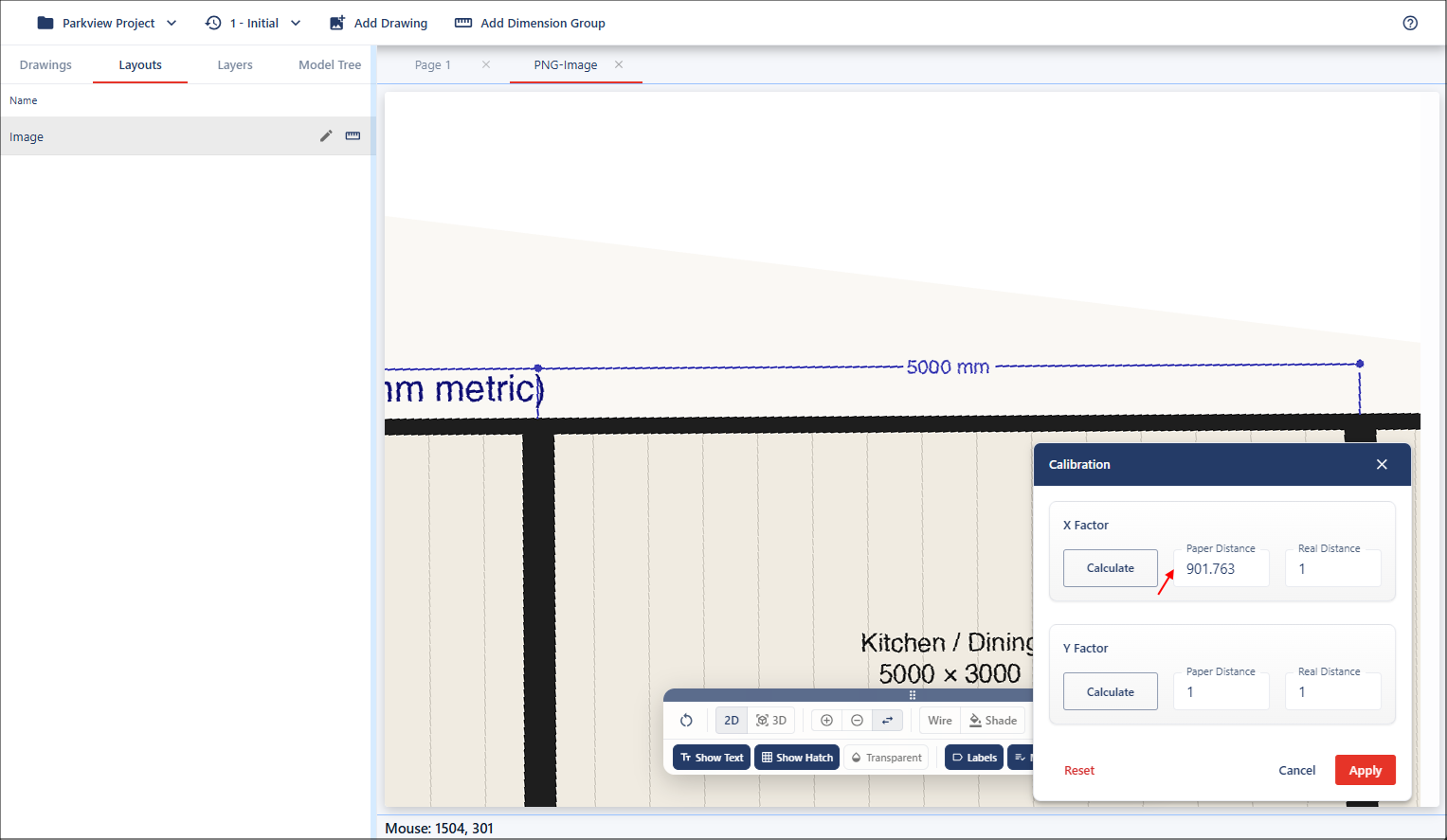
Release at the endpoint, and the measured value will automatically populate in the Paper Distance field as this is the measurement on the drawing.
Next, repeat this process for the Y Factor field. Click the Calculate button, but this time measure a vertical dimension for the Y factor value.

Once you have the paper distances calculated, you'll need to enter the real-world distances for both fields. In this case, the drawing shows the known measurement for both X and Y as 5000mm, so these values need to be added into the Real Distance fields.
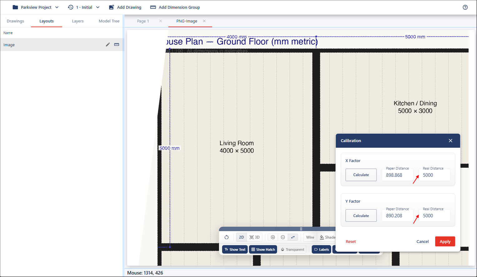
Once you're satisfied with the inputs, apply the calibration to update the drawing.