Calibrating
Calibrating Drawings in DimensionIQ
Calibration in DimensionIQ is essential because it ensures that any measurements you take from a drawing are accurate and reflect real-world dimensions. When you import a drawing, such as an image or raster file, the system does not automatically know the true scale of that drawing. Unlike CAD files that may already contain embedded scale data, these formats are essentially just visual representations made up of pixels.
Calibration solves this by linking a figured dimension on the drawing to its actual real-world size. If there are no figured dimensions on the drawing use a known dimension such as a door.
Key Reasons to Use Calibration
It establishes accurate scale, without calibration, the drawing has no reliable scale. Measurements taken would be arbitrary and incorrect.
It ensures measurement accuracy, once calibrated, tools like the Measure tool can return precise dimensions.
It works with non-scaled drawings, many drawings are not guaranteed to be printed or exported at a consistent scale. Calibration allows you to correct this and standardize the drawing.
It handles distorted or raster drawings, if a drawing has been stretched, rotated, or slightly distorted, calibration helps compensate for these inconsistencies so measurements remain reliable.
Determining the Calibration
Before you apply calibration in DimensionIQ, you need to identify a reliable reference measurement within your drawing. This step is critical because the accuracy of your entire measurement workflow depends on how well this reference is chosen.
What to look for when determining where to calibrate, you should look for a known, clearly defined dimension on the drawing. This could include:
- A labelled wall length
- Gridline spacing
- Structural elements with standard dimensions
- Any annotation that provides an exact measurement
Calibration should be performed after you have imported your drawing and opened a layout in the viewport.
If the drawing is not calibrated:
- Use the Measure tool to measure a known horizontal (X) distance in the drawing.
- Measure a known vertical (Y) distance as well.
- Enter the actual real distances for both the X and Y measurements.
- DimensionIQ will use these two values to calculate the correct calibration and account for any distortion in the drawing.
Paper Distance vs Real Distance
When calibrating a drawing in DimensionIQ, you are essentially comparing two different values, the paper distance (measured on the drawing) and the real distance (actual real-world measurement).
| Aspect | Paper Distance Value | Real Distance Value |
|---|---|---|
| Definition | The distance measured on the imported drawing inside DimensionIQ | The actual physical distance the drawing represents in the real world |
| Where it comes form | Measured directly using the Measure tool on the drawing | Taken from labels, design specifications or figured dimensions |
| Reliability before calibration | Not reliable on its own | Considered the true reference value |
| Purpose in calibration | Acts as the measured input value | Acts as the true reference value |
| Role in calibration | Used to calculate the scale factor | Used to define correct scale relationship |
Calibrating a Drawing
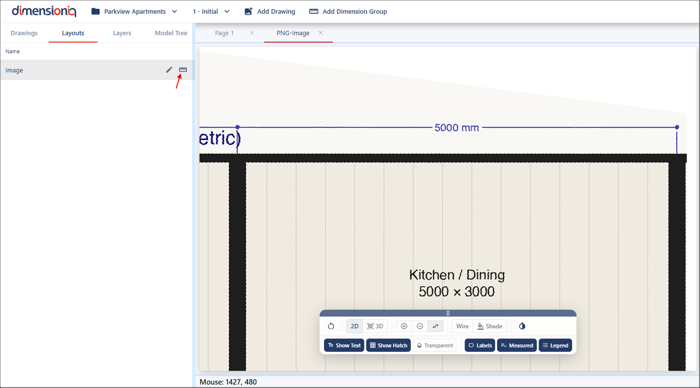
For greater accuracy, zoom in on a known measurement and click the Start Calibration button for the layout to open the Calibration Properties dialog
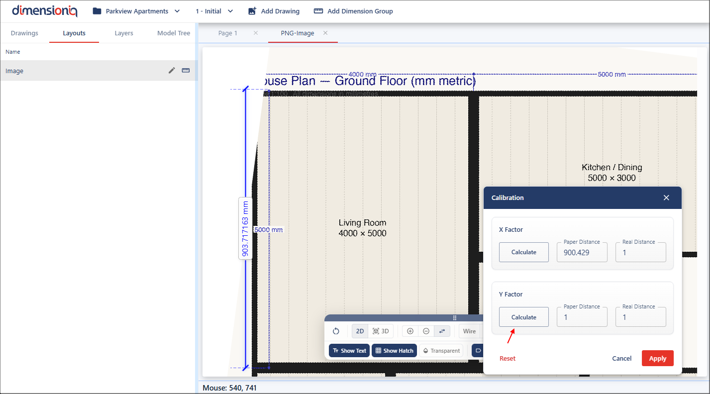
This dialog can easily be moved around the viewport, left-click and hold on the dialog header to move the dialog to a position that is not in your way. With the dialog open, there's no need to manually select the Measure tool. Instead, click the Calculate button for the X Factor fild and this will activate the measurement mode.
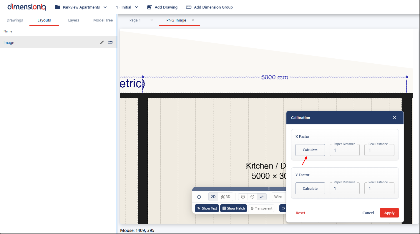
Move to the starting point of the dimension, then left click and hold while dragging your mouse along the measurement. There is no snap functionality when working with a drawing that has no geometry applied.
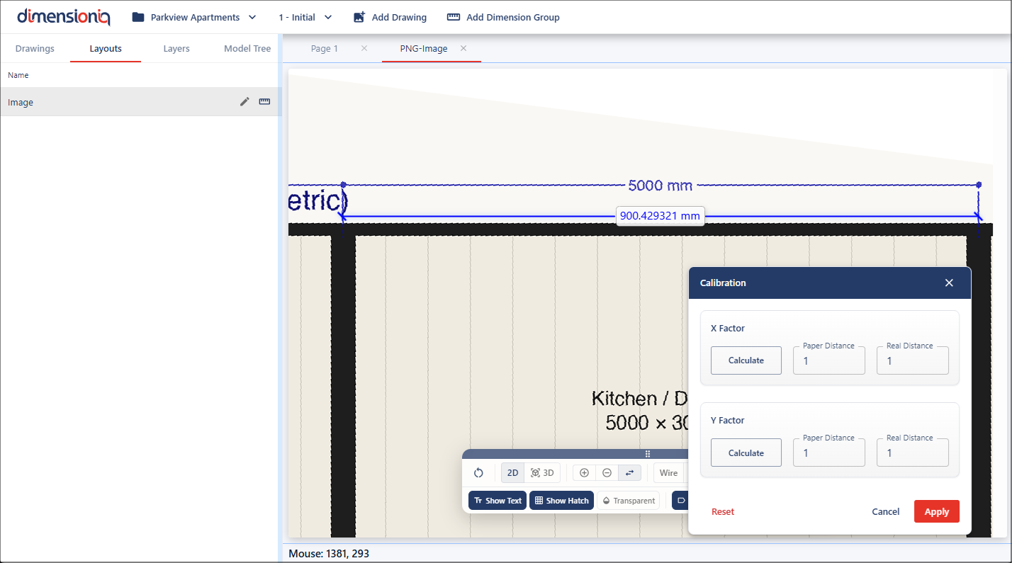
Release at the endpoint, and the measured value will automatically populate in the Paper Distance field as this is the measurement on the drawing. The Paper Distance value is used to capture the measured distance on the drawing, which DimensionIQ then compares against the real distance to calculate the correct calibration scale.

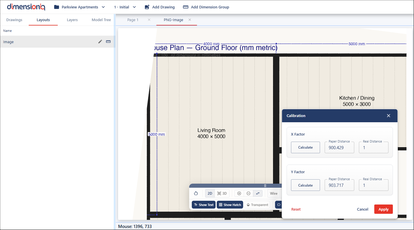
This needs to be repeated for the Y Factor field. Click the Calculate button for the field, but this time measure a vertical dimension for the Y factor value. Once again it will need to be a figured dimension in the drawing.
Once you release your mouse at the endpoint, the measured value will automatically populate in the Paper Distance field for the Y factor.
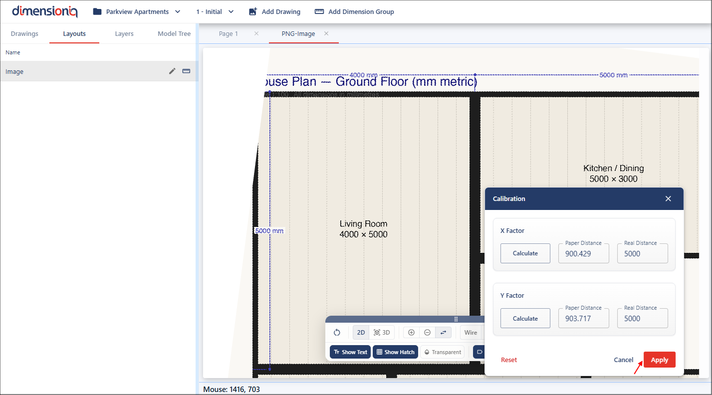
The real-world dimensions for both fields need to be entered. In this case, the drawing shows 5000 millimetres for both the X and Y measurements on the known dimension lines. These values need to be added into the Real Distance fields as they are the real-world measurements. The Real Distance value is used to enter the actual known measurement from the real-world, which DimensionIQ uses alongside the paper distance to determine the correct scale for the drawing.
Once you have added the inputs, click the Apply button to update the drawing.
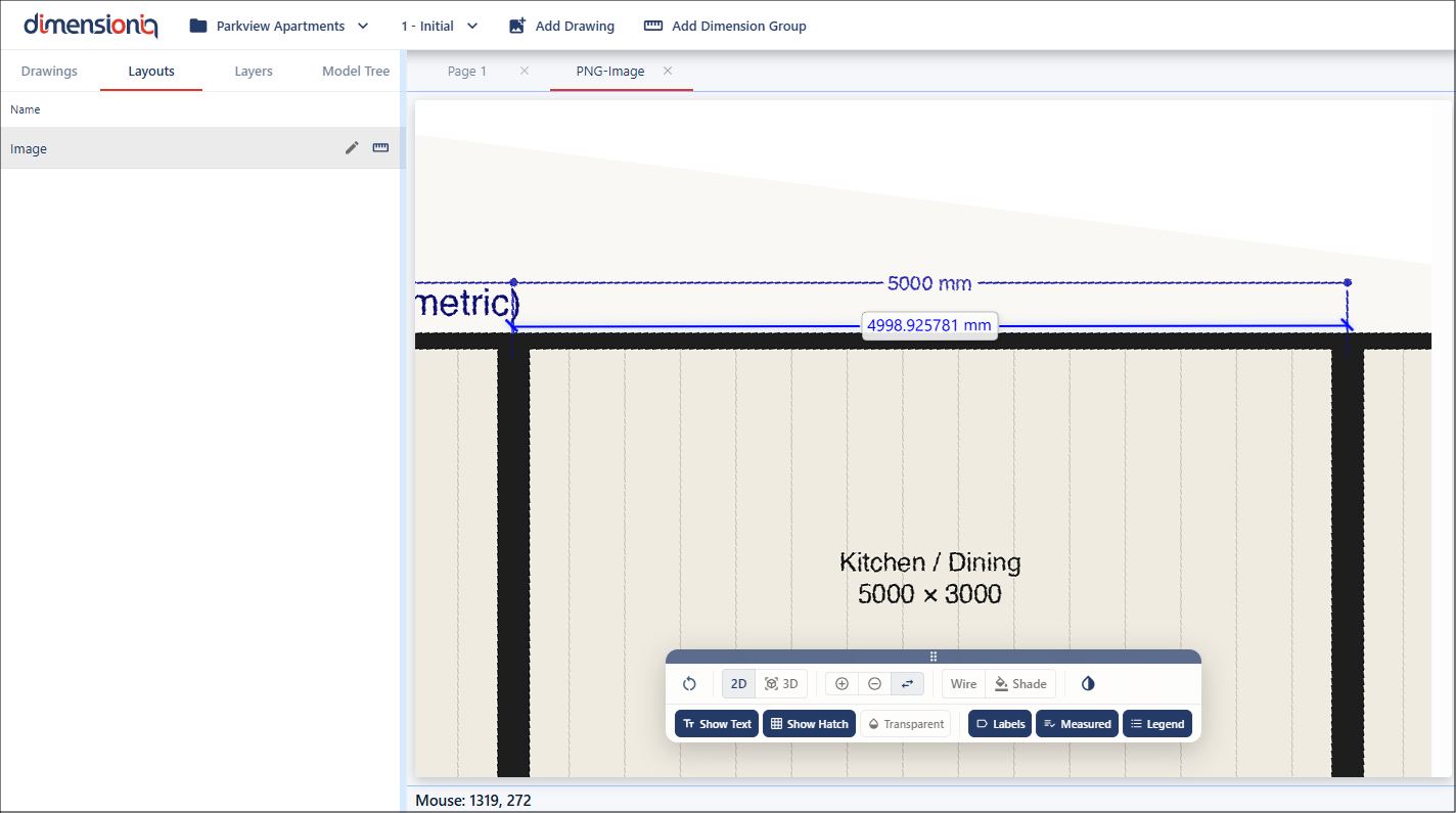
The calibration can now be verified using the Measure tool. As you can see, the measurement now matches the expected real-world value, confirming that the calibration has been successfully applied.
It is always important to check your scales before you measure as you can't always rely on the information on the drawing.