Calibrating and Scaling
What You'll Learn
In this tutorial, you will learn how to:
By the end of the tutorial, you'll be able to prepare any drawing for accurate and reliable measurement in DimensionIQ.
It is assumed that you have created a project in your host application.
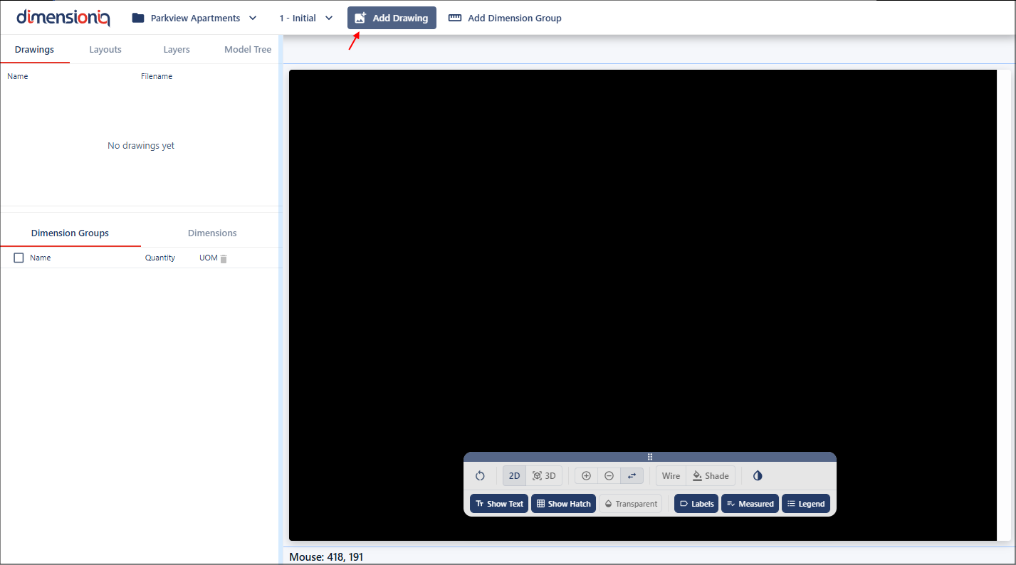
Step 1: Importing Drawings
Let's begin by importing a drawing. In this tutorial, we will be working with 2D drawings.
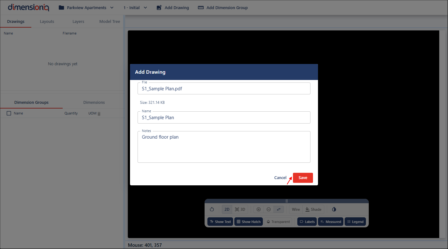
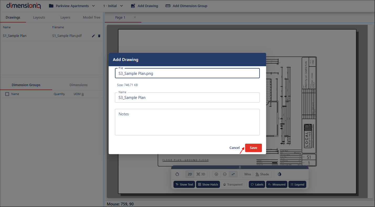
To import a drawing, click the Add Drawing button to open the the Drawing Properties dialog.
From here, select your drawing file by clicking in the File field. Once selected, the Name field will automatically populate using the file name without the extension. You can keep this default or edit it if required. The Notes field is optional and can be used to add any additional context or information about the drawing.
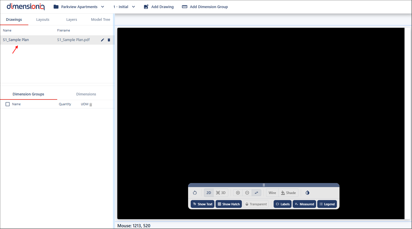
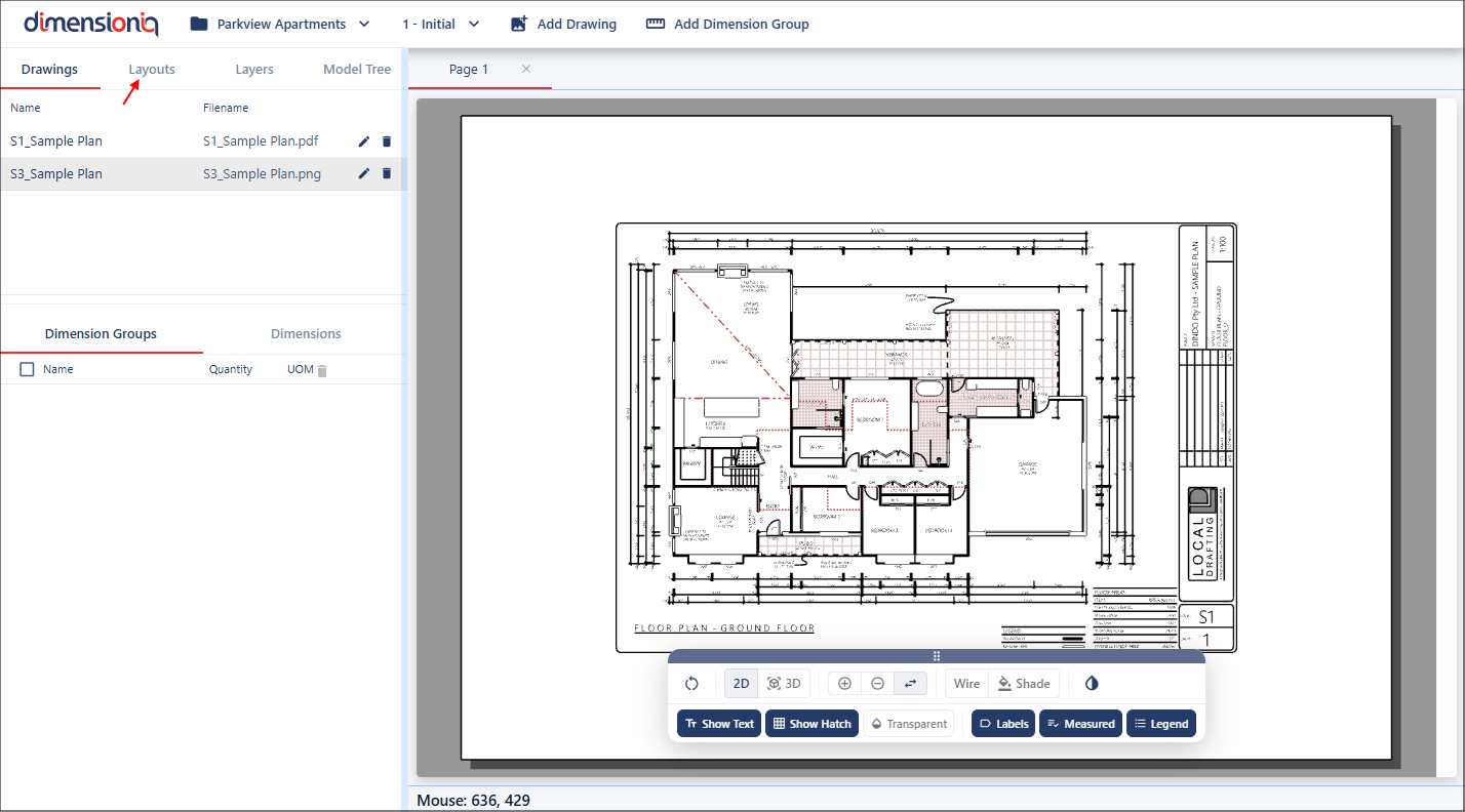
Once you have saved the import, the drawing will appear in the left-hand menu.
Step 2: Working With Layouts
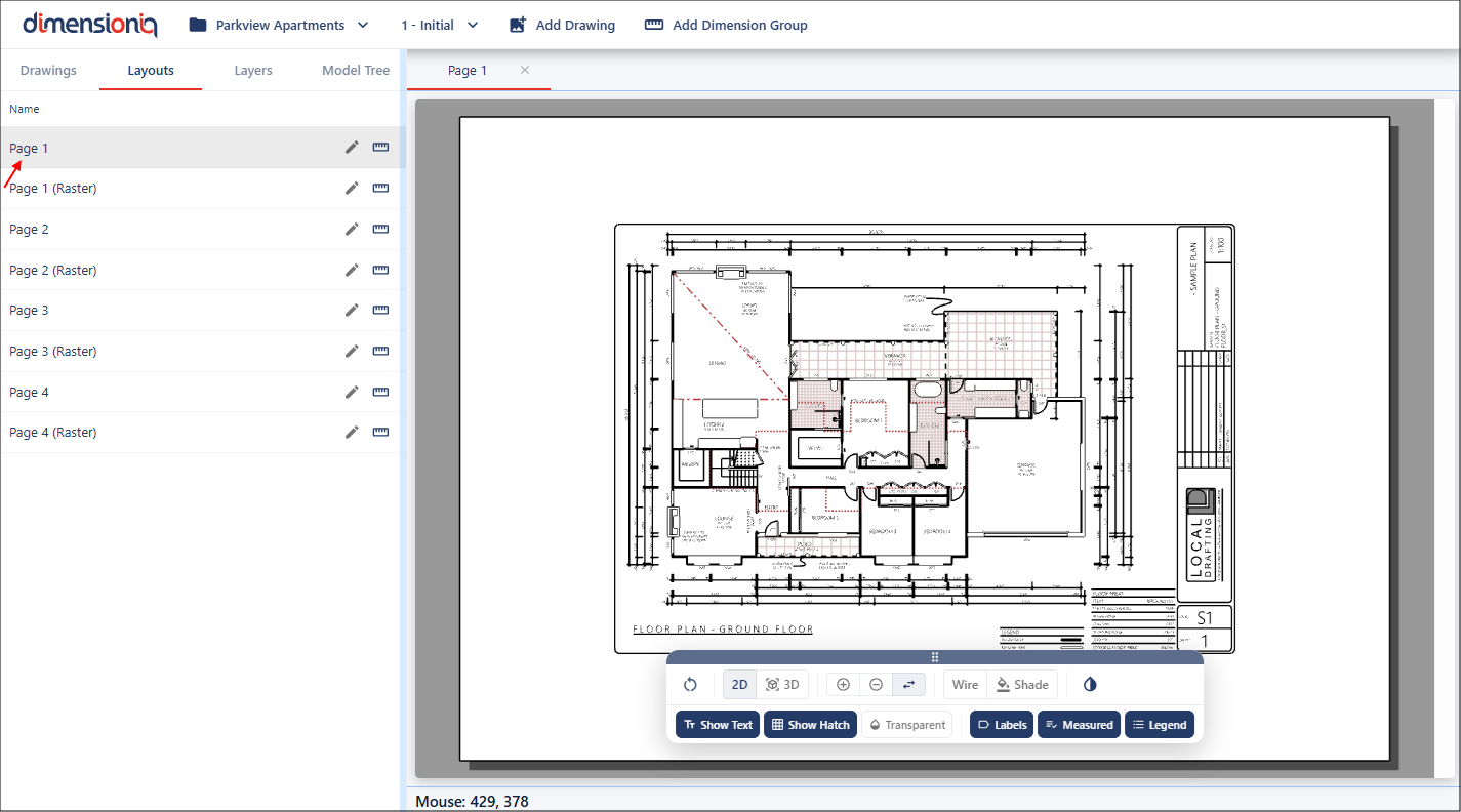
Drawings may contain multiple sheets or pages. In DimensionIQ, these are referred to as layouts. To view them, select the Layouts tab.

Each available layout will be listed here. Simply click on a layout to open it in the viewport and begin working with it.
Step 3: Applying Scale
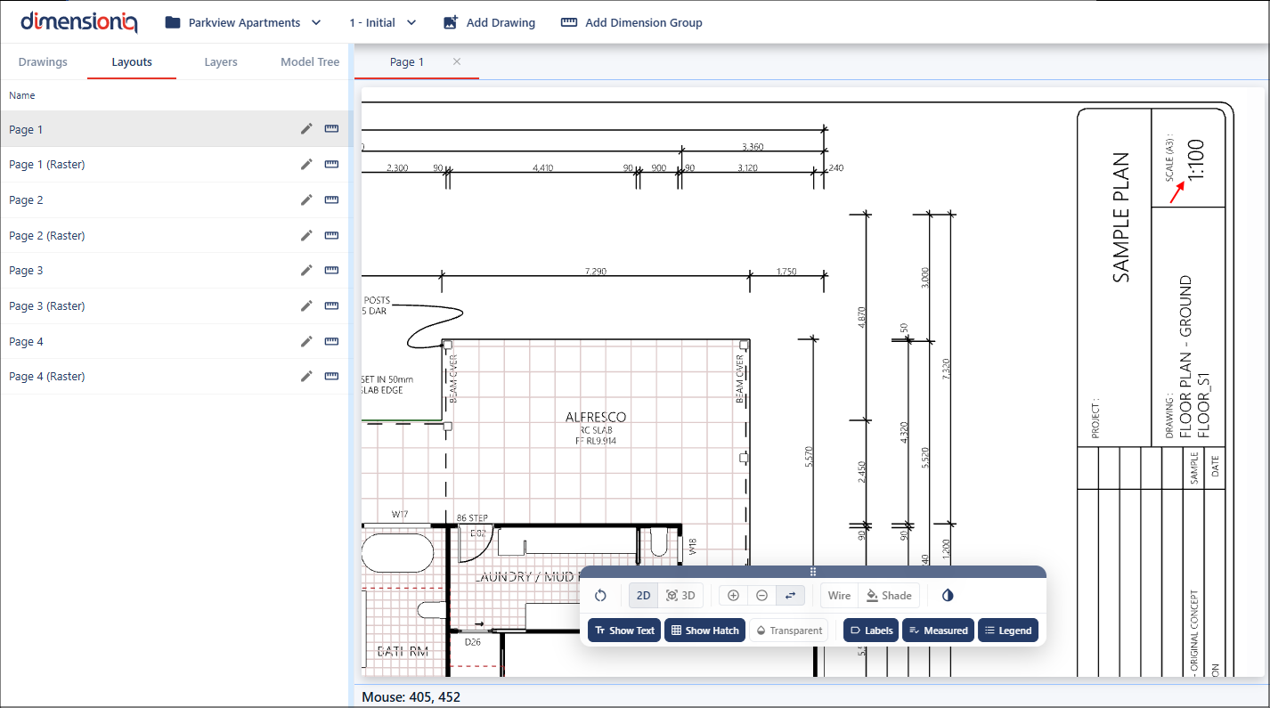
Scaling ensures that all measurements reflect real-world dimensions. Without correct scaling, even small inaccuracies can result in major errors in quantities, estimates, and planning. We can see on this drawing plan that it has a scale of 1:100. That means for for every 1 millimetre on the drawing represents 100 millimetres in the real world.
You can use the Measure tool to validate whether a drawing has been correctly scaled. When working with a drawing that has geometry the Measure tool will snap to existing points. These snap points ensure higher accuracy when selecting endpoints. As you move your cursor the tool will automatically detect and lock onto valid geometry points where available.
To use the Measure tool, zoom into a known dimension, right click in the viewport and select Measure.

As you move your cursor, it will snap to points on the geometry, this is indicated by the red target marker.
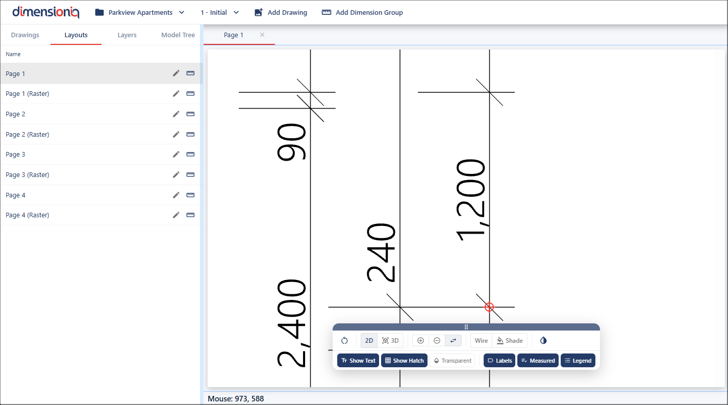
Left click and hold to start your measurement, then move to the next point where it will snap again to complete the measurement.
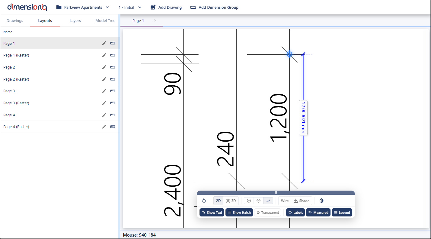
We can now see this drawing is not to scale, as the known dimension is 1200mm not 12mm, this must be adjusted before continuing.
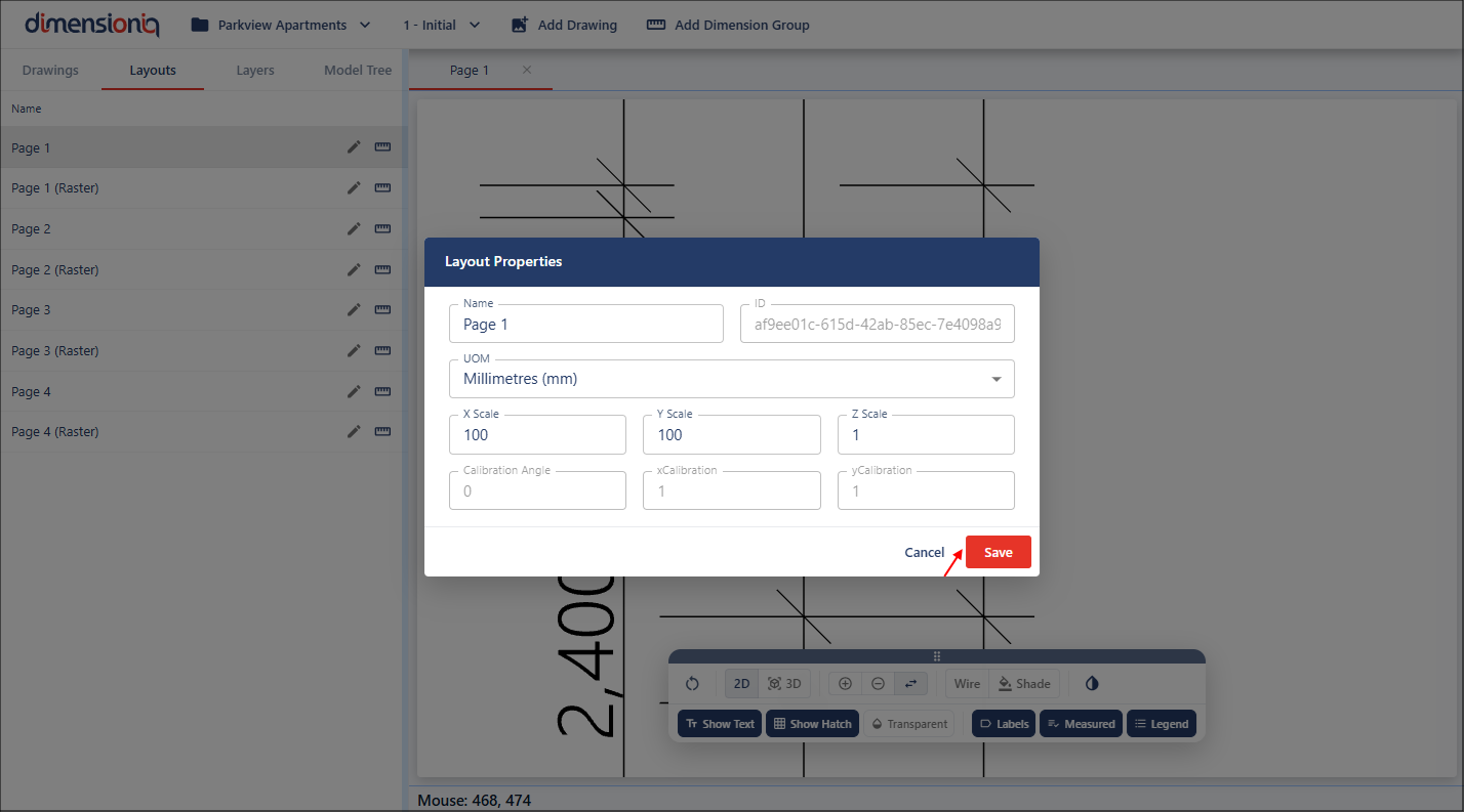
To fix this, open the Scale Properties dialog by clicking the Edit button next to the layout in the left-hand menu.

From here, set the X scale value to 100. The Y scale value will automatically default to the same value unless you adjust it. Once completed you can save your scale porperties.
Once your scaling has been saved, the Measure tool can be used again and you can see the layout is correctly scaled and ready to take measurements.

Step 4: Rotating Drawings
Another drawing is imported into the system.
Once saved, it is listed under the other drawing, select the Layouts tab for this drawing.
This drawing only has one layout which is a PNG image, select this image and it will open in the viewport in a new tab. This is not a good drawing and is not aligned correctly. We can fix this with the Rotate tool.

Zoom into a logical line on your drawing, for example, this known line on the drawing. Right click in the viewport, select Rotate and then select Rotate To Line.
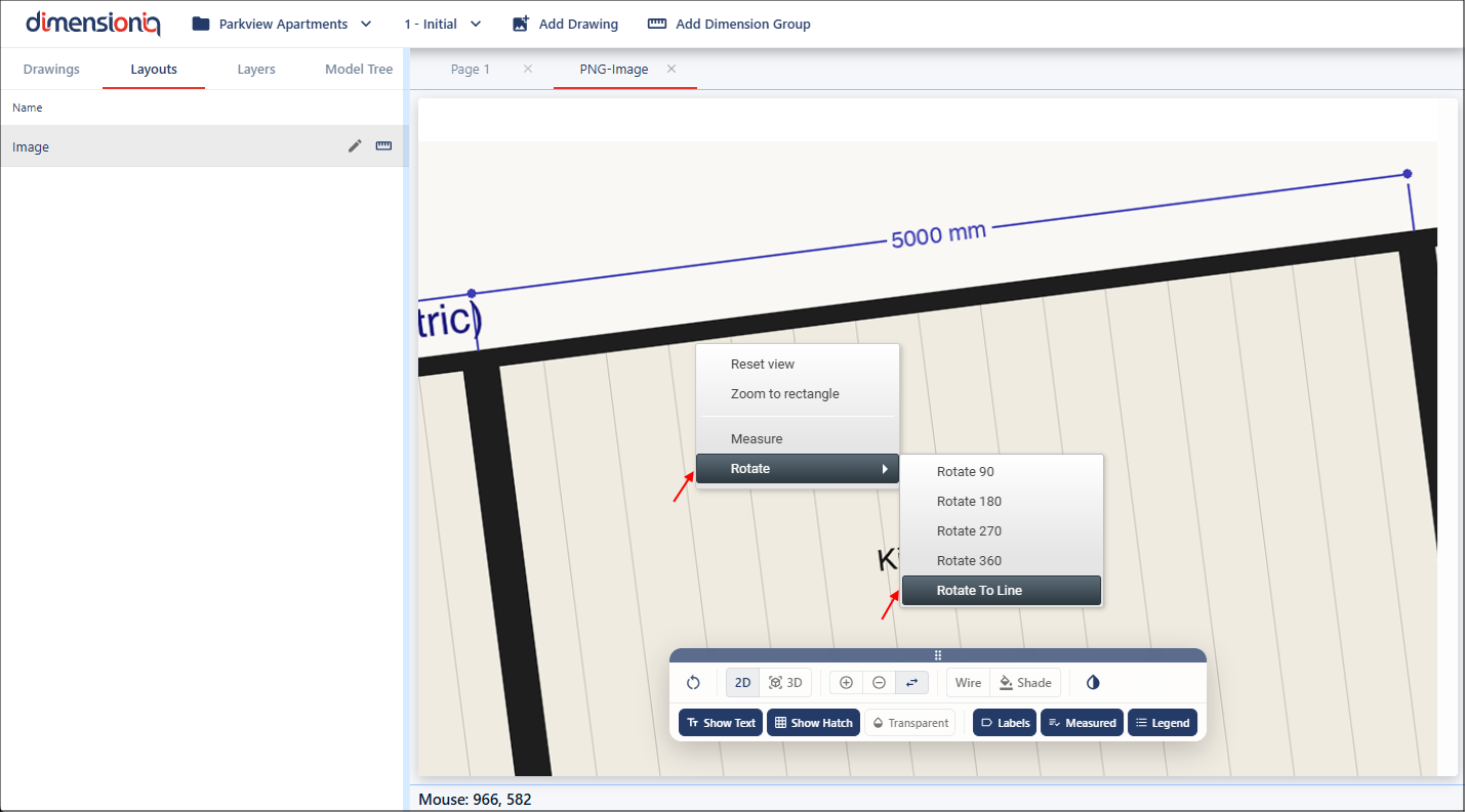
Next, move your mouse to this logical line, left click and hold, slightly move your mouse to see the dotted line DimensionIQ provides to line up with.
Continue to move your mouse until your drawing line and the dotted line are aligned, release the mouse.
The drawing will now be correctly straightened and ready for calibration.
Step 5: Calibrating Drawings
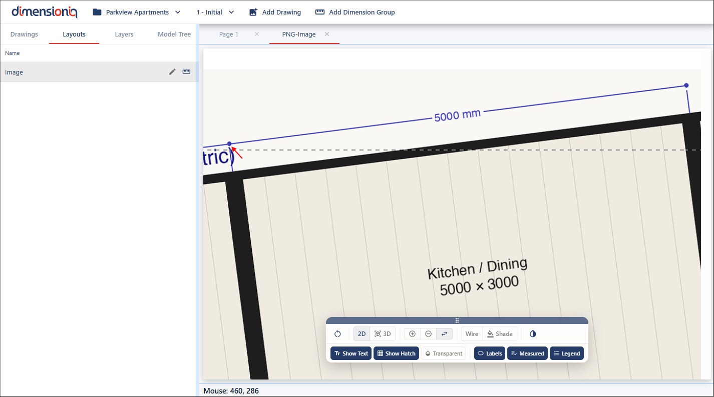
In the real-world, drawings aren't always perfect. You may come across plans that are not drawn to scale, stretched or distorted, or provided as raster files such as images. In these situations, standard measurements won't give you accurate results. This is where calibration becomes essential. By manually calibrating the drawing, you can realign and correctly scale it using known reference points and dimensions.
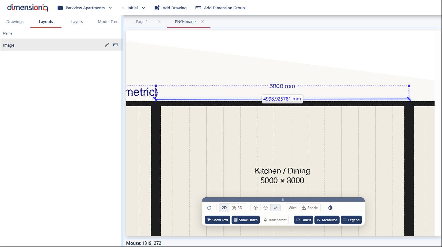
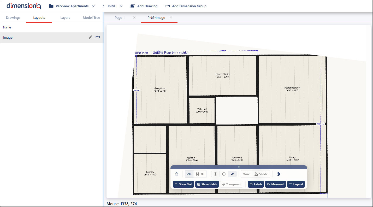
For calibration, you need to focus on a known dimension within the drawing. This could be a common reference, such as a door, but in this example, we'll use a known dimension line provided in the drawing.
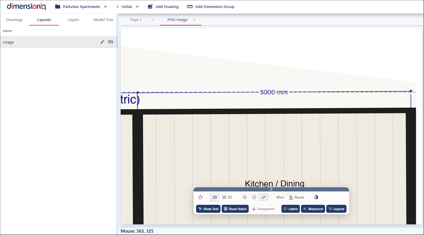
Start by zooming in on the dimension. There is no snap functionality when working with a drawing that has no geometry applied. We'll use the Measure tool again and we can see this drawing is not scaled properly, this will need to be fixed.
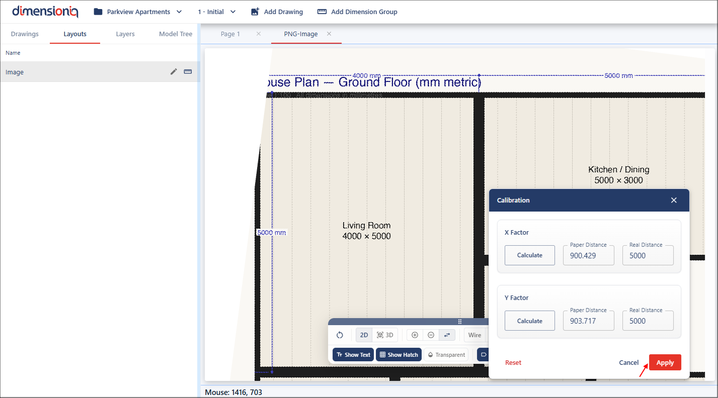
Click the Start Calibration button for the layout you are working with to open the Calibration Properties dialog.
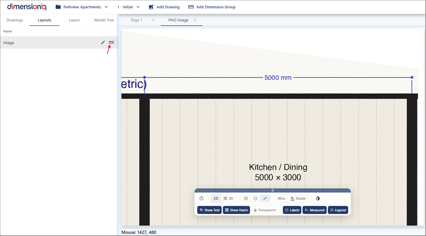
This dialog can easily be moved around the viewport, left-click and hold on the dialog header to move the dialog to a position that it is not in your way. With the dialog open, there’s no need to manually select the Measure tool. Instead, click the Calculate button for the X Factor field. This will activate measurement mode.
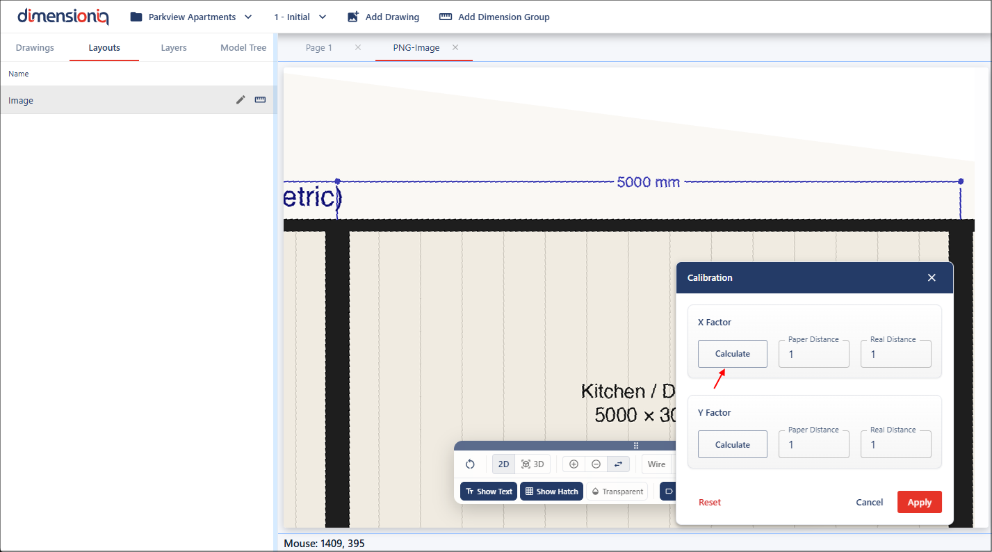
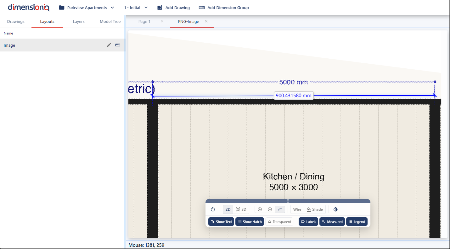
Move to the starting point of the dimension, then left click and hold while dragging along the measurement.
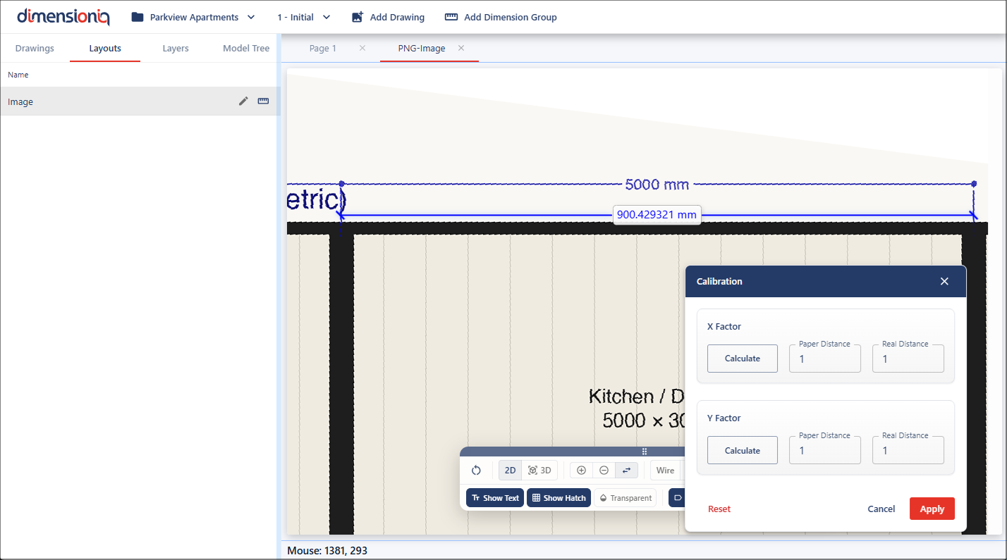
Release at the endpoint, and the measured value will automatically populate in the Paper Distance field as this is the measurement on the drawing.

Next, repeat this process for the Y Factor field. Click the Calculate button, but this time measure a vertical dimension for the Y factor value. In this example, we’ll use another dimension line shown on the drawing.
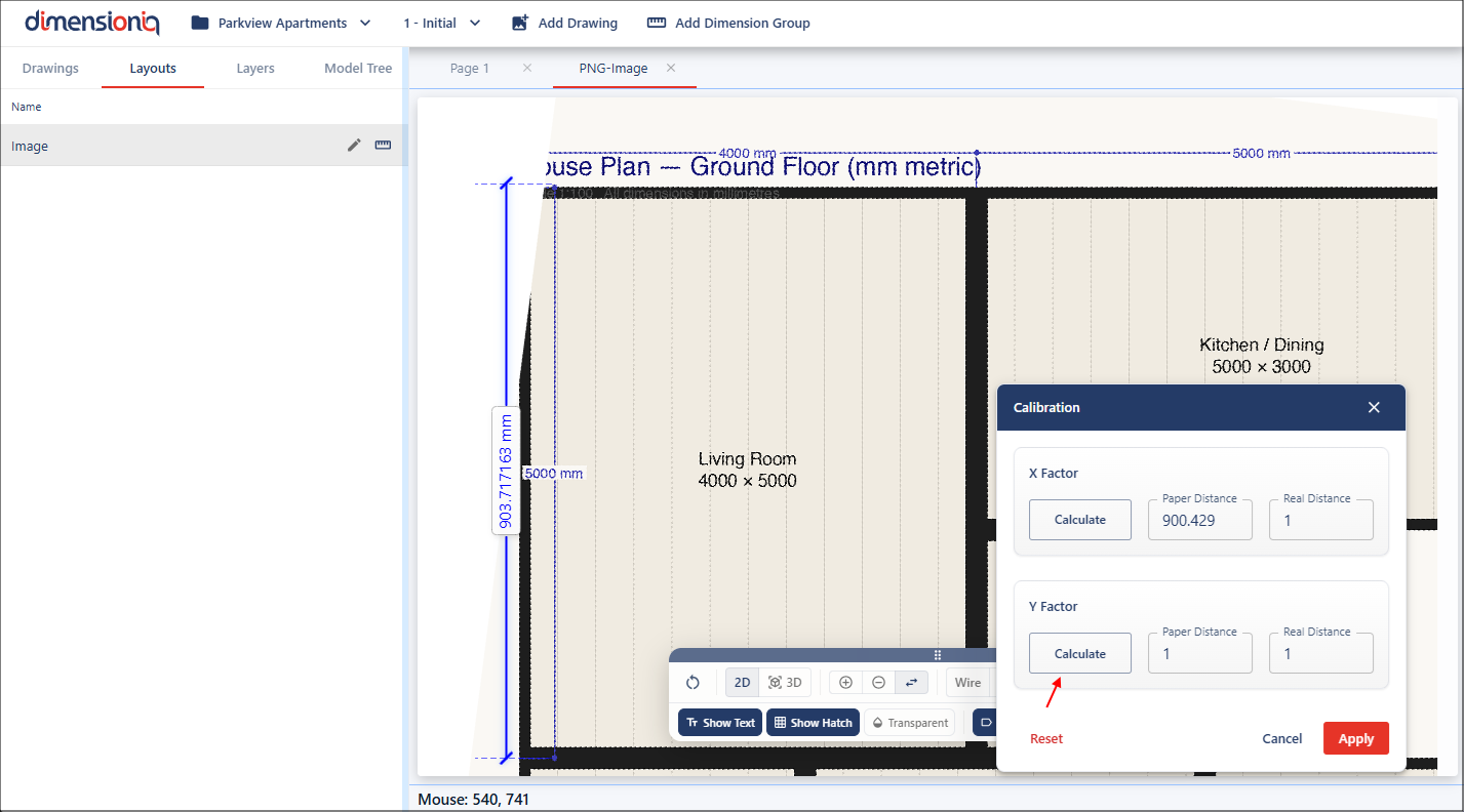
Once completed, the measurement will populate in the Y Factor Paper Distance field. You’ll need to enter the real-world dimensions for both fields. In this case, the drawing shows 5000 millimetres for both X and Y measurements, so these values need to be added into the Real Distance fields as these are the real-world measurements.
Once you’re satisfied with the inputs, apply the calibration to update the drawing.
We can now verify the calibration using the Measure tool. As you can see, the measurement now matches the expected real-world value, confirming that the calibration has been successfully applied.
It is always important to check your scales before you measure as you can’t always rely on the information on the drawing.