Project Setup
Overview
This Project Setup example demonstrates how a project can be structured when DimensionIQ is integrated into a host application. In this setup, DimensionIQ operates as a specialized takeoff engine within the broader system, allowing users to perform measurements, calculations, and visual analysis without leaving the main application environment.
The host application manages core functionality such as project data, user interactions, and workflows, while DimensionIQ handles dimensioning, segment control, and takeoff logic. Data flows seamlessly between the two, ensuring that any measurements or changes made in DimensionIQ are immediately reflected in the overall project.
This integrated approach provides a unified user experience, reduces duplication of work, and allows advanced takeoff capabilities to be embedded directly into existing business processes.
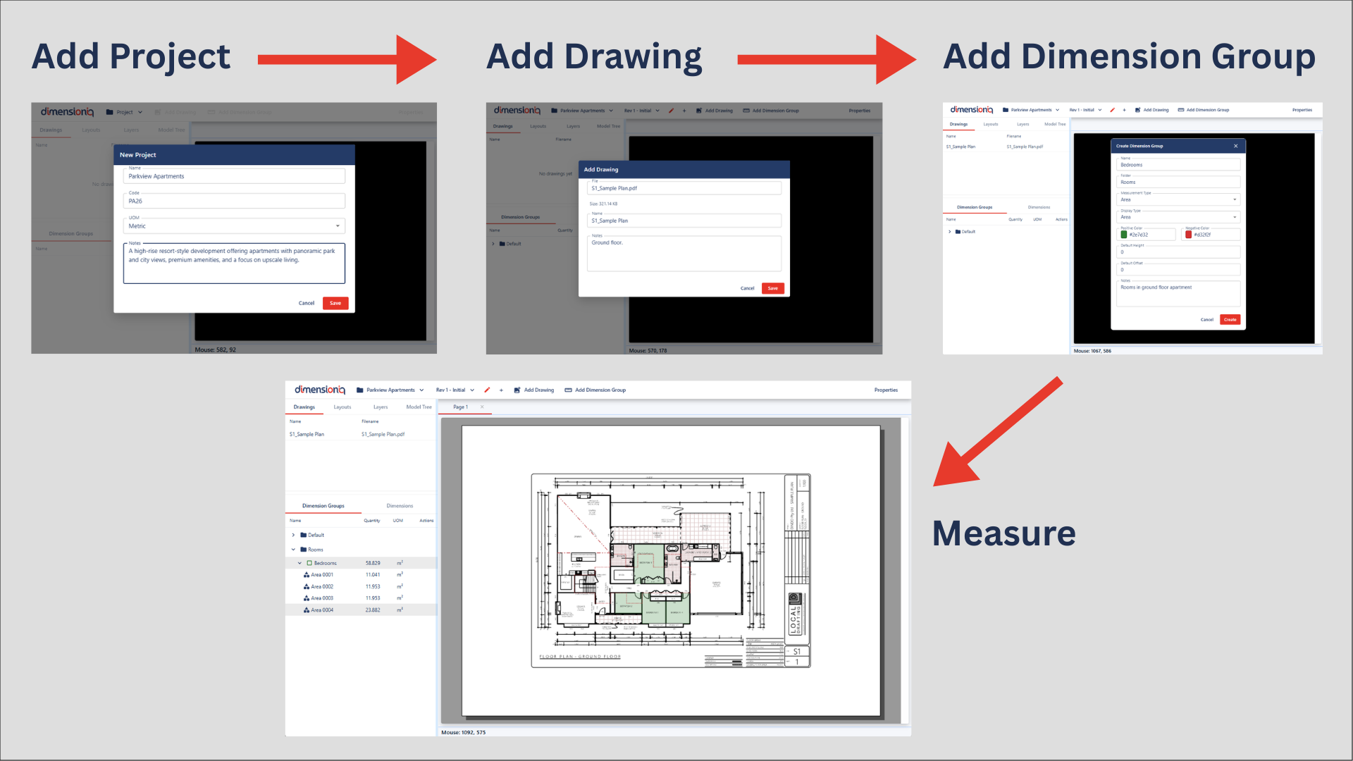
Project Setup Workflow
This guide outlines the basic setup workflow required to begin using DimensionIQ. Completing these steps establishes the structure needed to organize drawings and measurements within the system.
The DimensionIQ takeoff follows a simple hierarchy:
Project -> Drawings -> Dimension Groups -> Dimensions
- Projects contain all drawings and measurements
- Drawings are the plans used for takeoffs
- Dimension Groups act as folders to organize measurements taken from drawings
- Dimensions are your actual takeoff measurements
A project must be created before drawings can be added, and drawings must exist before measurements can be taken.
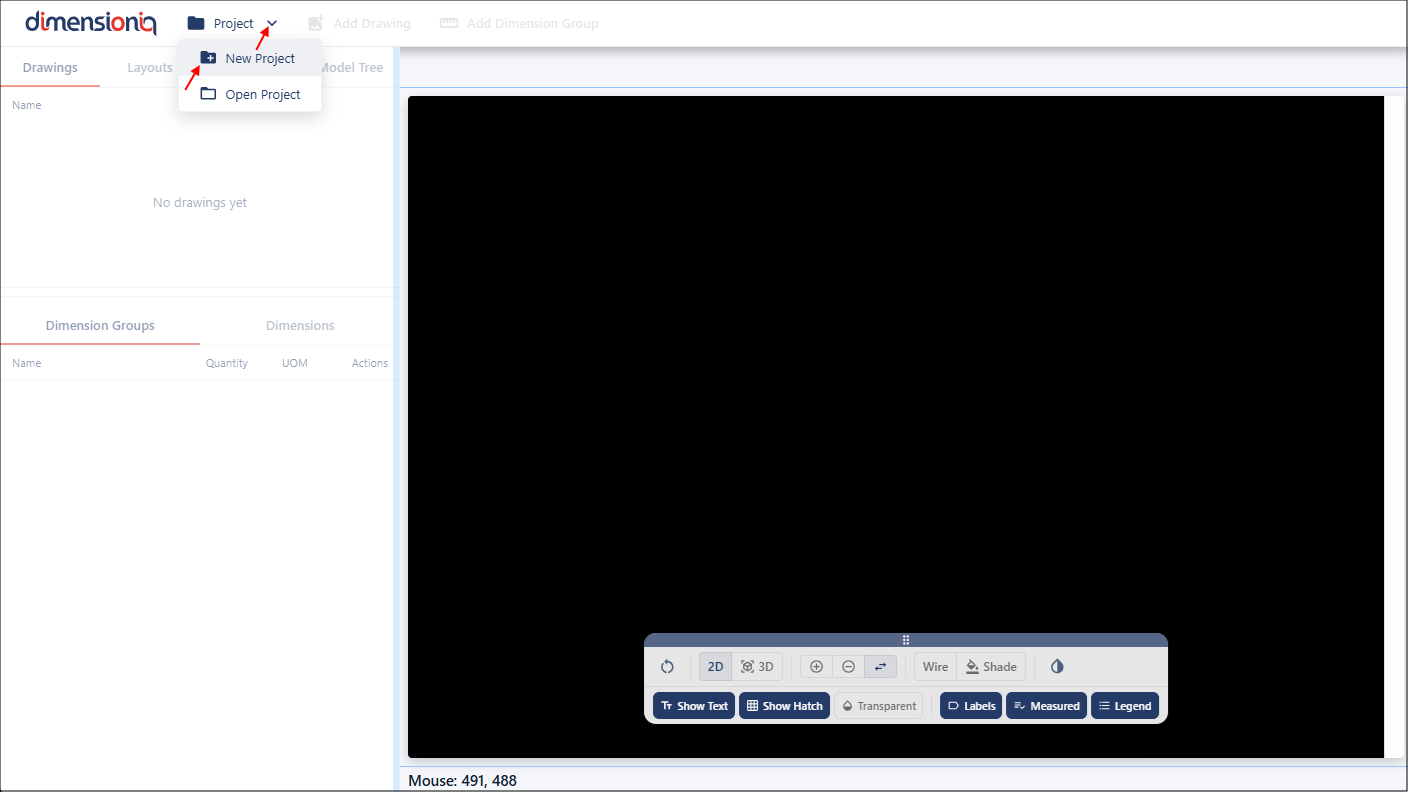
Step 1: Add a Project
Creating a project is the first step in setting up your workspace in DimensionIQ. A project acts as the top-level container that holds all drawings, folders, and measurements associated with a specific job or estimate.
Only one project can be open at a time, so starting a new project establishes the working environment for your takeoff.
In the toolbar on the left-hand-side, locate the Project tab and select New Project from the dropdown menu.
The Project Properties dialog will open, enter a name for your project, and optionally you can add a code and notes about your project. If you are not using the default Metric measuring system, you can select Imperial in the UOM (Unit of Measurement) field.
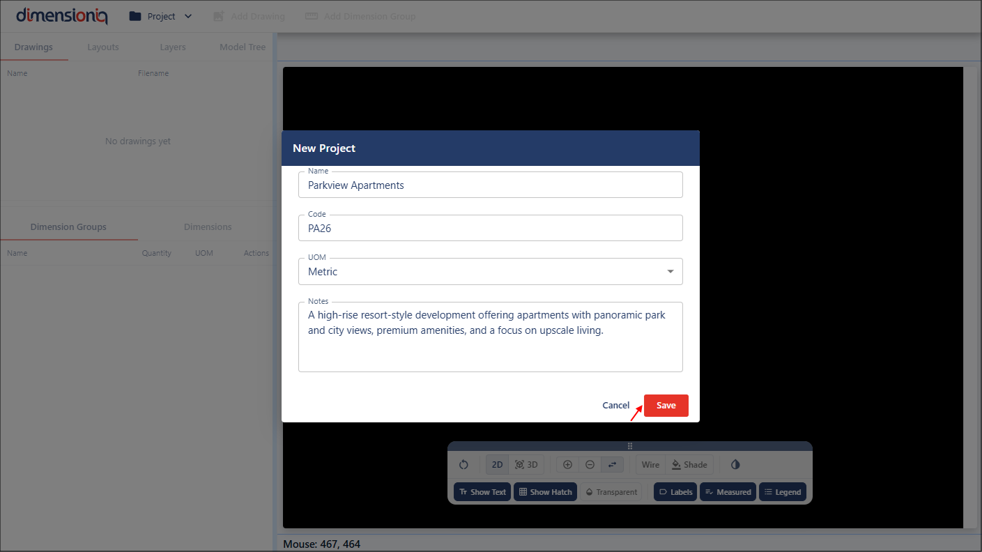
When you click the Save button, the project will be available in the left-hand-side of the toolbar, where its properties can be edited from the project dropdown menu if required.

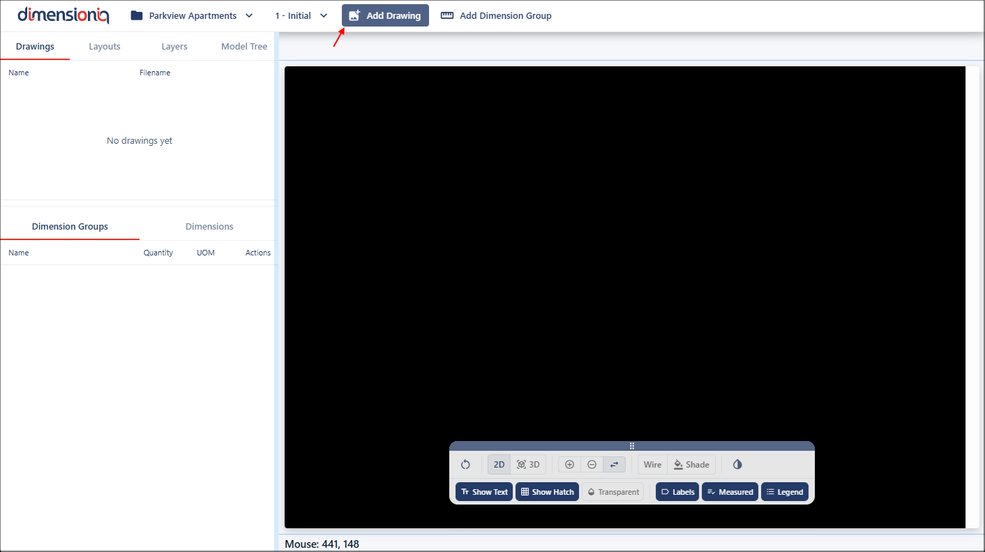
Step 2: Add a Drawing
After adding a project, the next step is to add drawings to the project. Drawings contain the plans or layouts that will be used for measurement. Each drawing file can contain multiple layouts, allowing you to measure different sheets within the same project.
Click the Add Drawing button in the toolbar to open the Drawing Properties dialog.
Select your electronic drawing file from your computer or network by clicking in the File field. You can change your drawing name or leave the settings as is, and optional notes about your drawing file can be added.
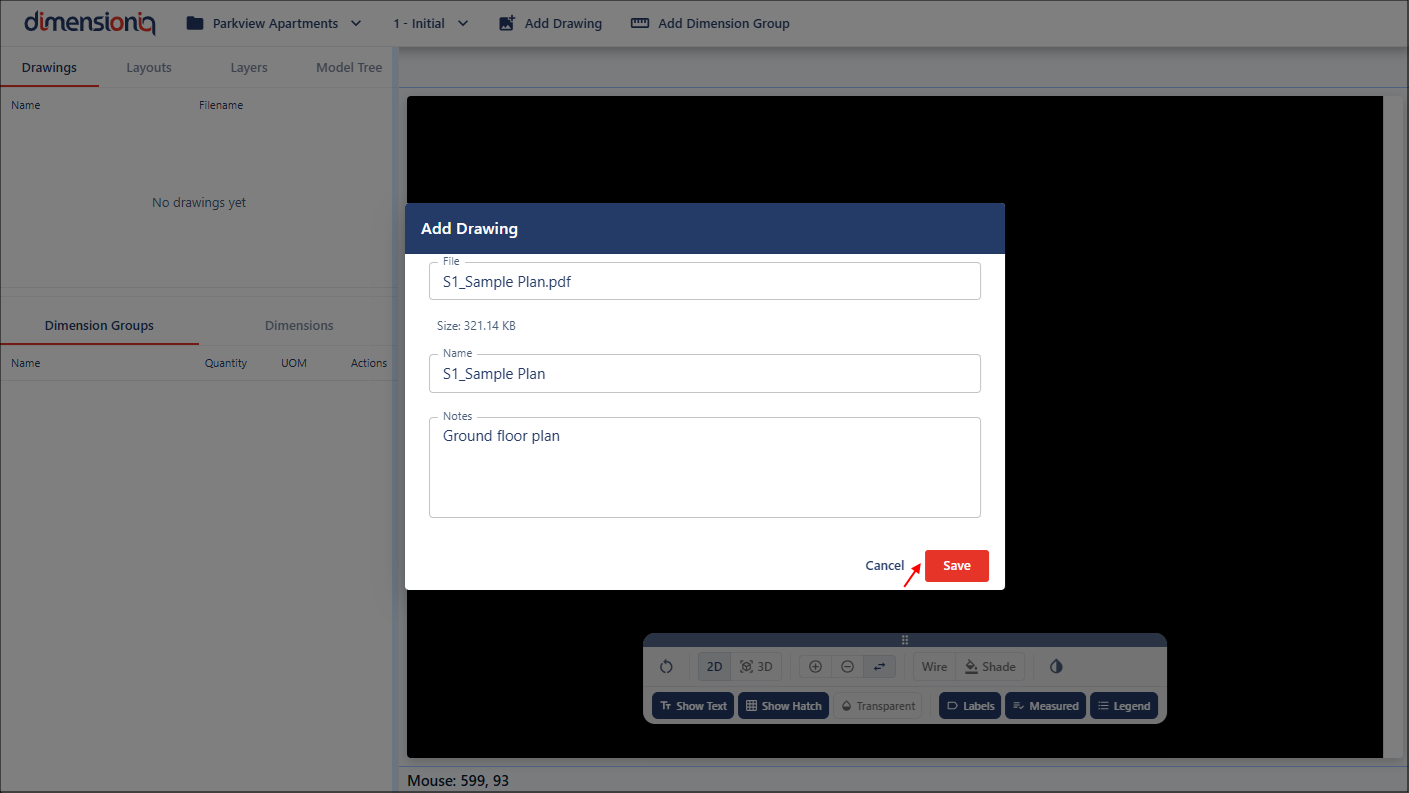
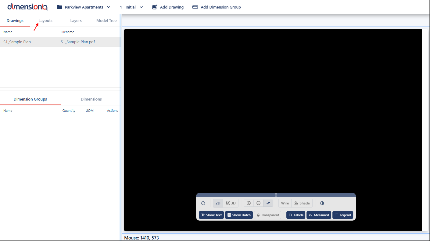
When you click the Save button, the drawing will be available in the left-hand-side menu.

Step 3: Open Drawing Layouts
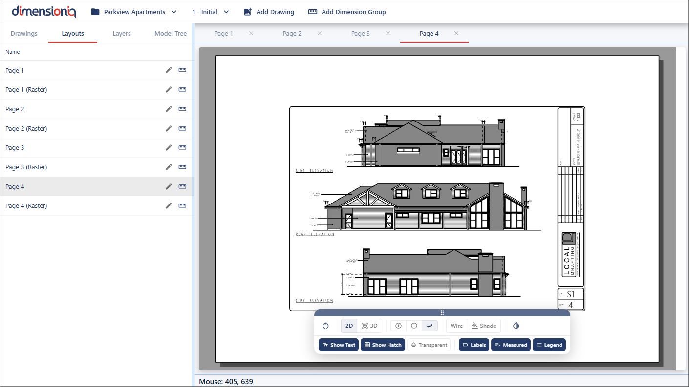
Most drawing files contain multiple pages or sheets, these will be available in the Layouts tab. Click the tab to open the menu holding the layouts in a drawing file.
Before taking measurements, you must open the specific layout/s you want to work with, click on a layout from the list to open the page.
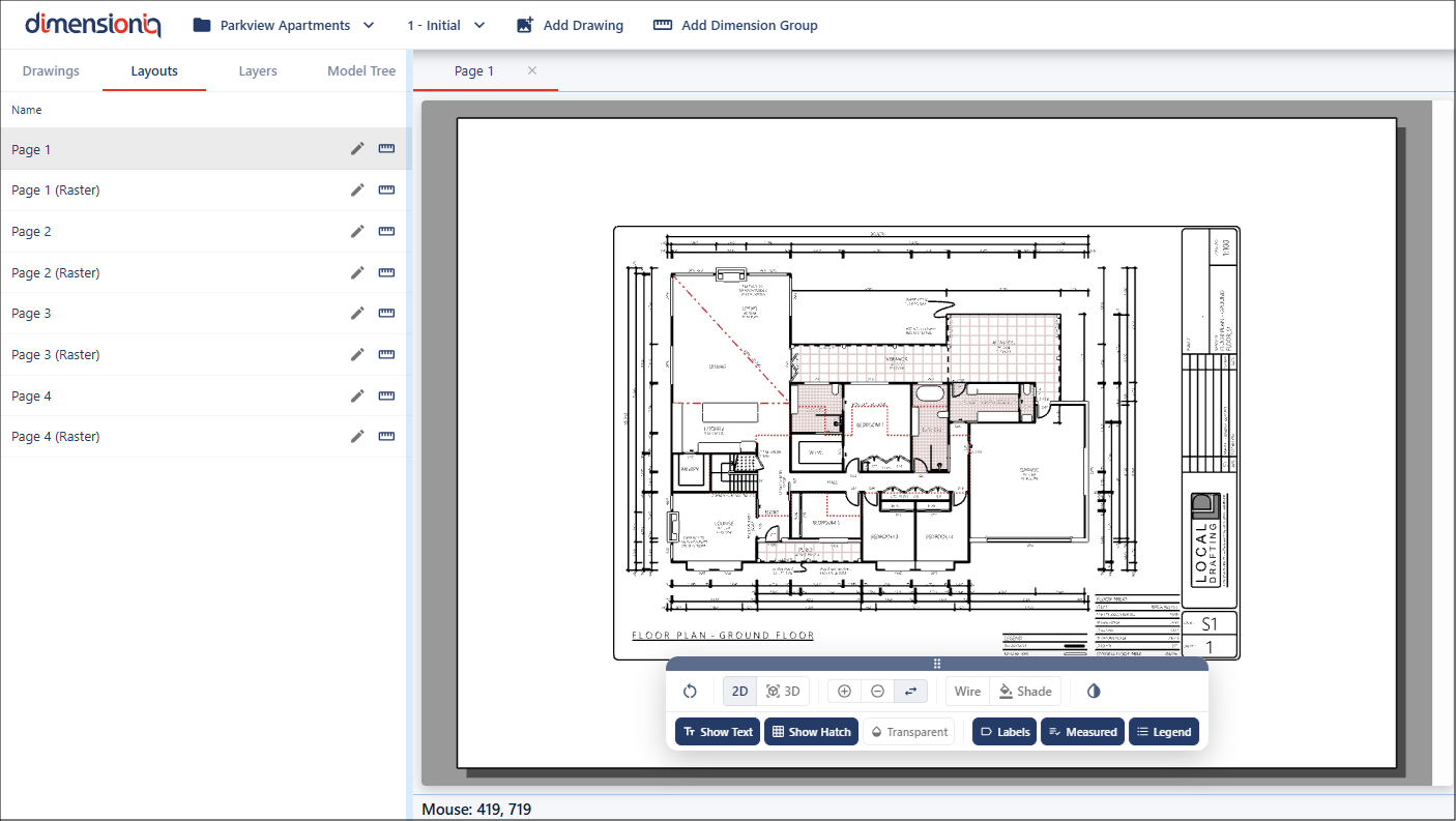
DimensionIQ allows multiple pages to be opened simultaneously, making it easier to switch between different layouts of a plan without closing and reopening layouts, and enabling you to to easily move between drawings while working. Each layout will be held in its own tab available at the top of the viewport.
Step 4: Verify the Scale
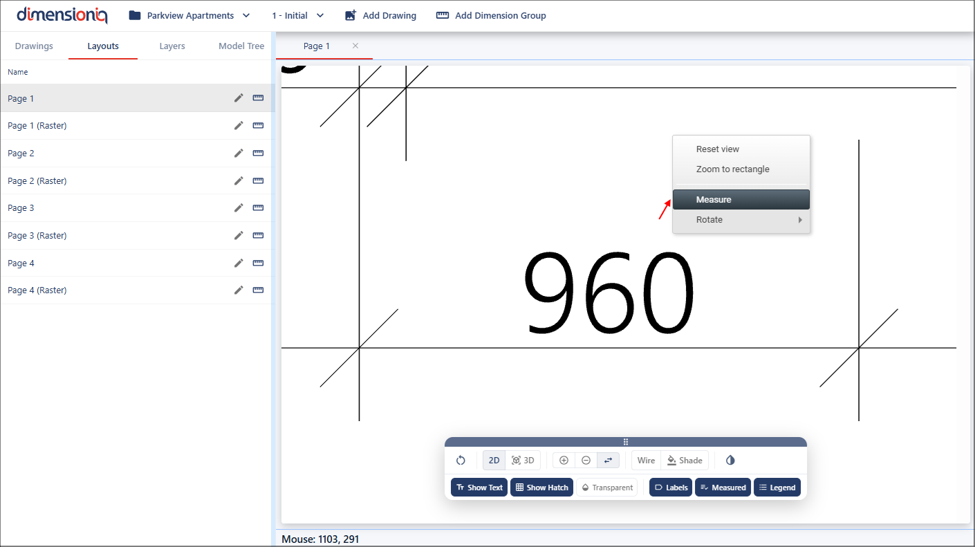
Before taking measurements, it is essential to ensure the drawing layout scale is correct. In most cases, you will have the scale provided on the drawing, however, you can use our Measure tool to verify that the scale is correct.
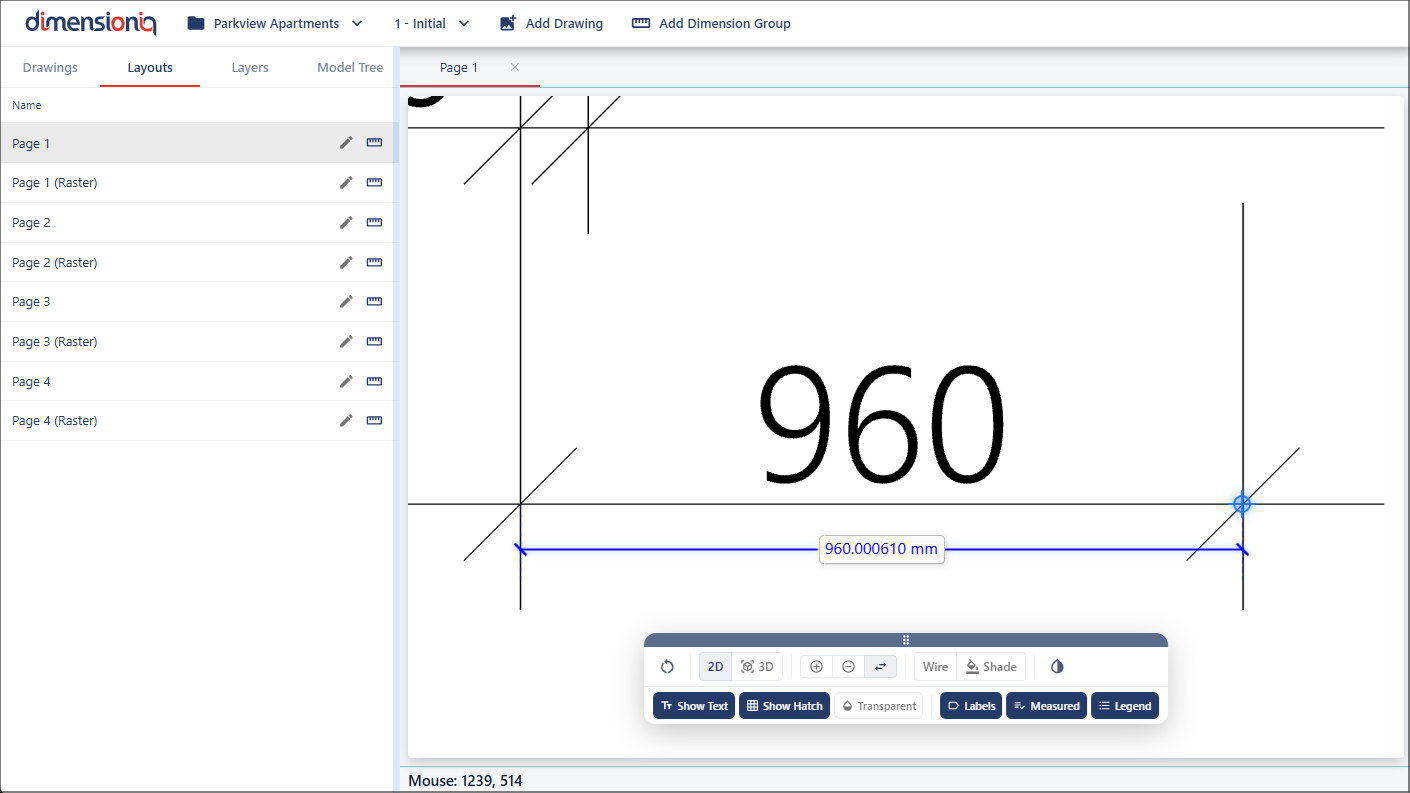
Select a figured dimension on the drawing and zoom in to get a more accurate measurement. Right click in the viewport and select Measure.
Click once at the start point of the selected dimension and as the mouse cursor is moved a marker line displays the distance between the start point and the current cursor position.
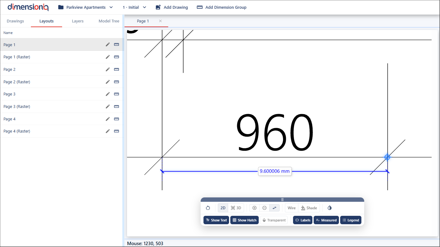
If the measurement matches the expected value when scaled, for example, measuring 1mm on the drawing corresponds correctly to 100mm in the real-world scale for 1:100, the drawing scale is correct.
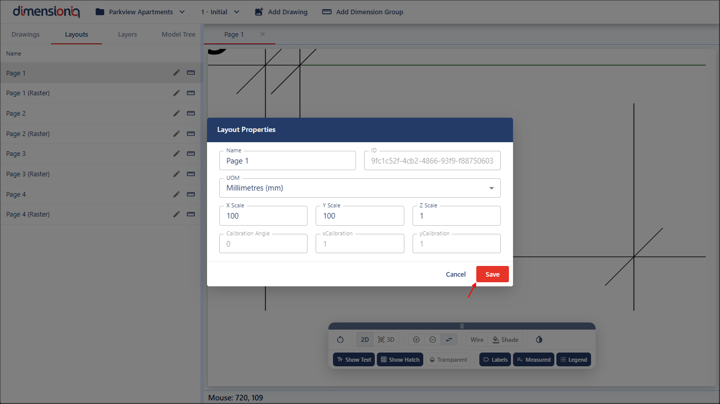
To enter the scale values, click the Edit button next to the layout name to open the Layout Properties dialog.
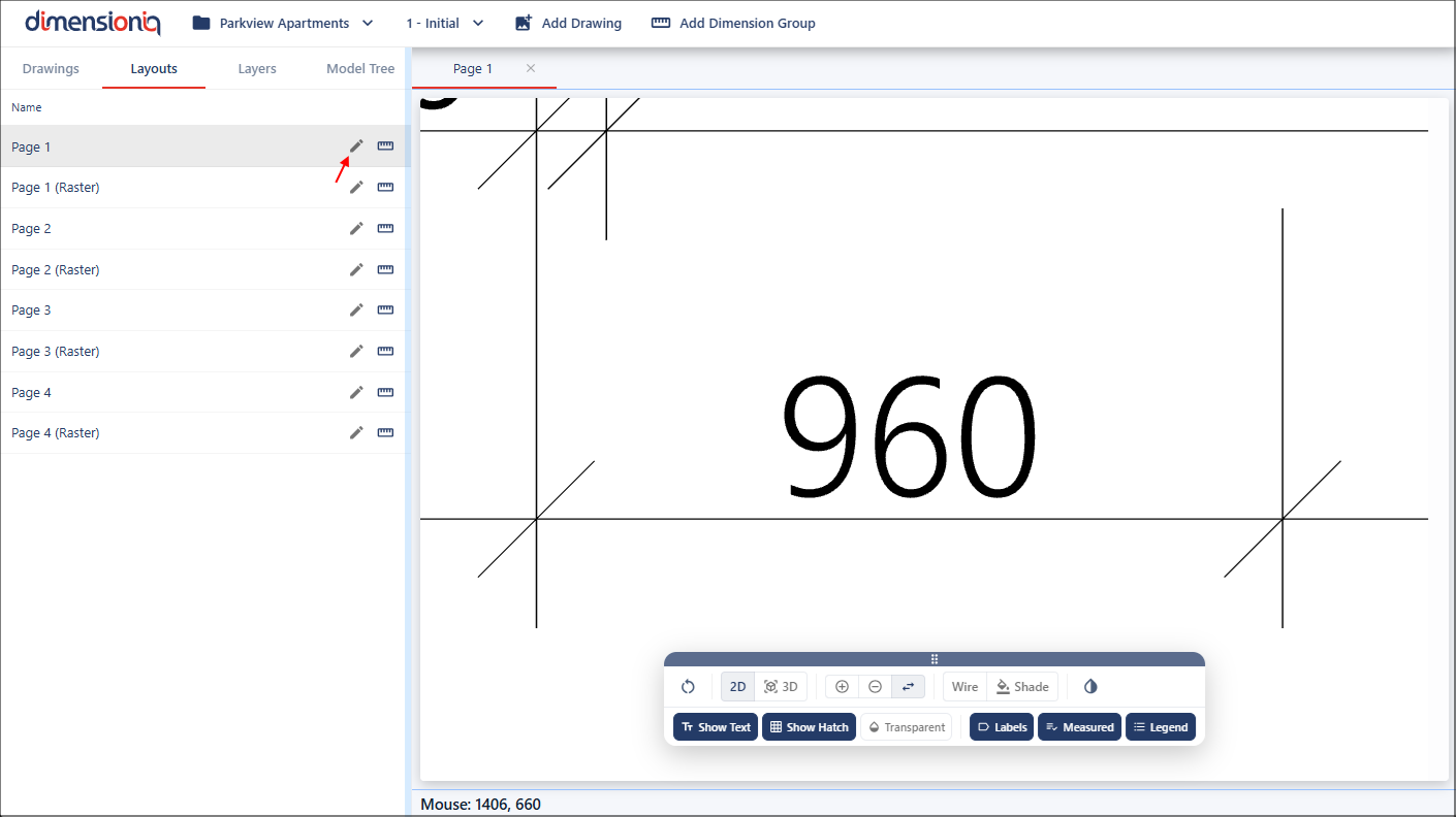
Enter the X scale and Y scale values corresponding to the verified drawing scale, for example, 100 both X and Y if the scale is 1:100. The Y Scale field will default from the X scale value, however, this can be edited.
Once the scale values have been saved, you can use the measure tool again to see this applied.
Step 5: Create Dimension Groups
Dimension groups are created to hold and organize measurements taken from a drawing. When creating a dimension group, you must assign it to a folder by selecting an existing folder or creating a new one. Folders help organize related dimension groups. For example, you might create a folder named Walls, with dimension groups such as Internal and External to measure the length of each wall or the perimeter of a room.
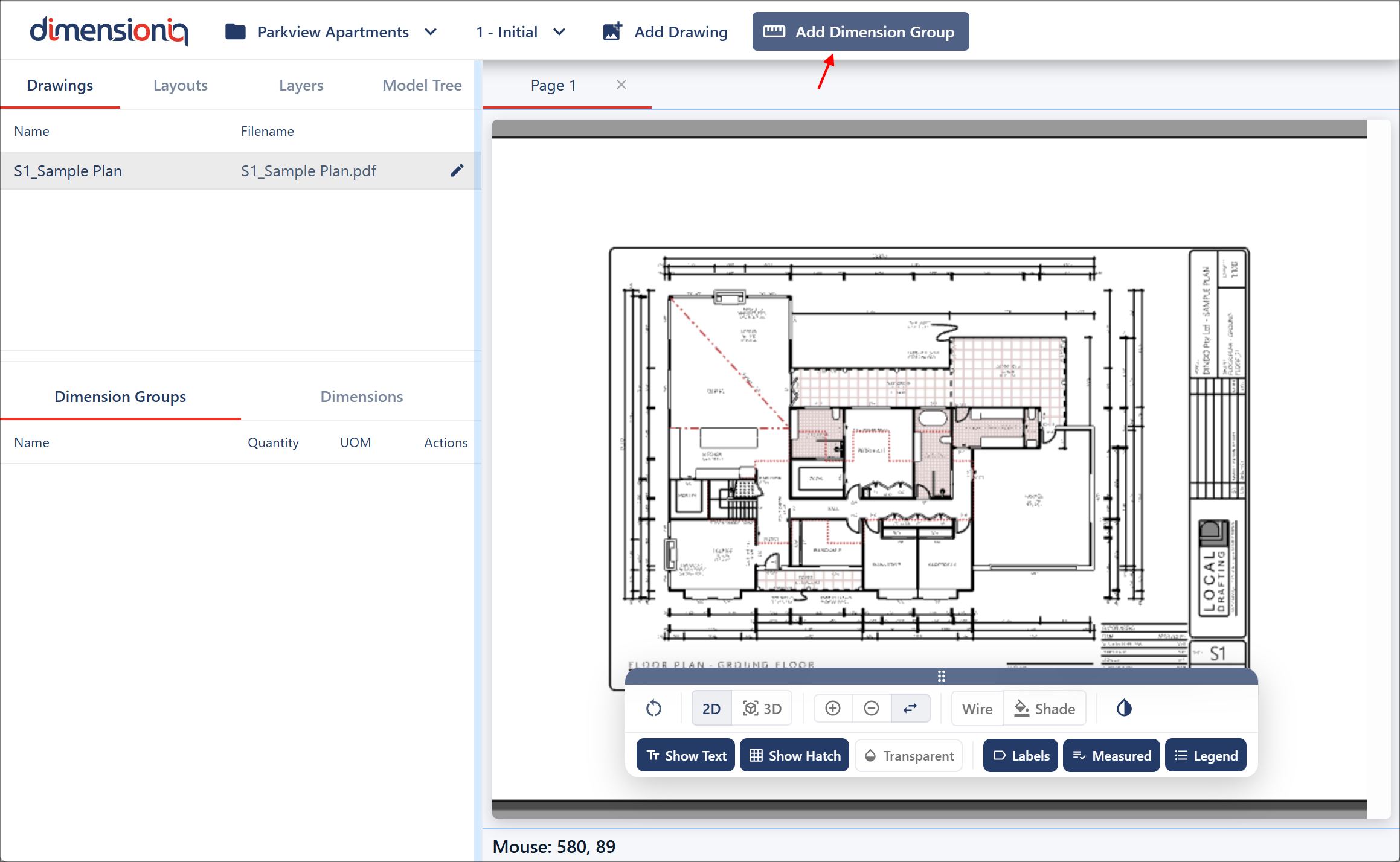
To create a dimension group, click the Add Dimension Group button in the toolbar to open the Dimension Group Properties dialog.
Give the group a name and either select an existing folder or create a new folder by giving the folder a name in the Folder field. Each dimension group requires a measurment type and a display type. The measurement type defines how the quantity is calculated, while the display type determines which value is shown in the user interface. If the two types are different, for example, Area as the measurement type and Length as the display type, both values will be visible when hovering over the dimension on the drawing. In the left menu, however, the value will correspond to the display type.
The colors you select are used to display the dimension markers on the drawing, making it easier to distinguish different dimension groups.
You may also notice default fields in the window, which are optional and not required during the initial setup.
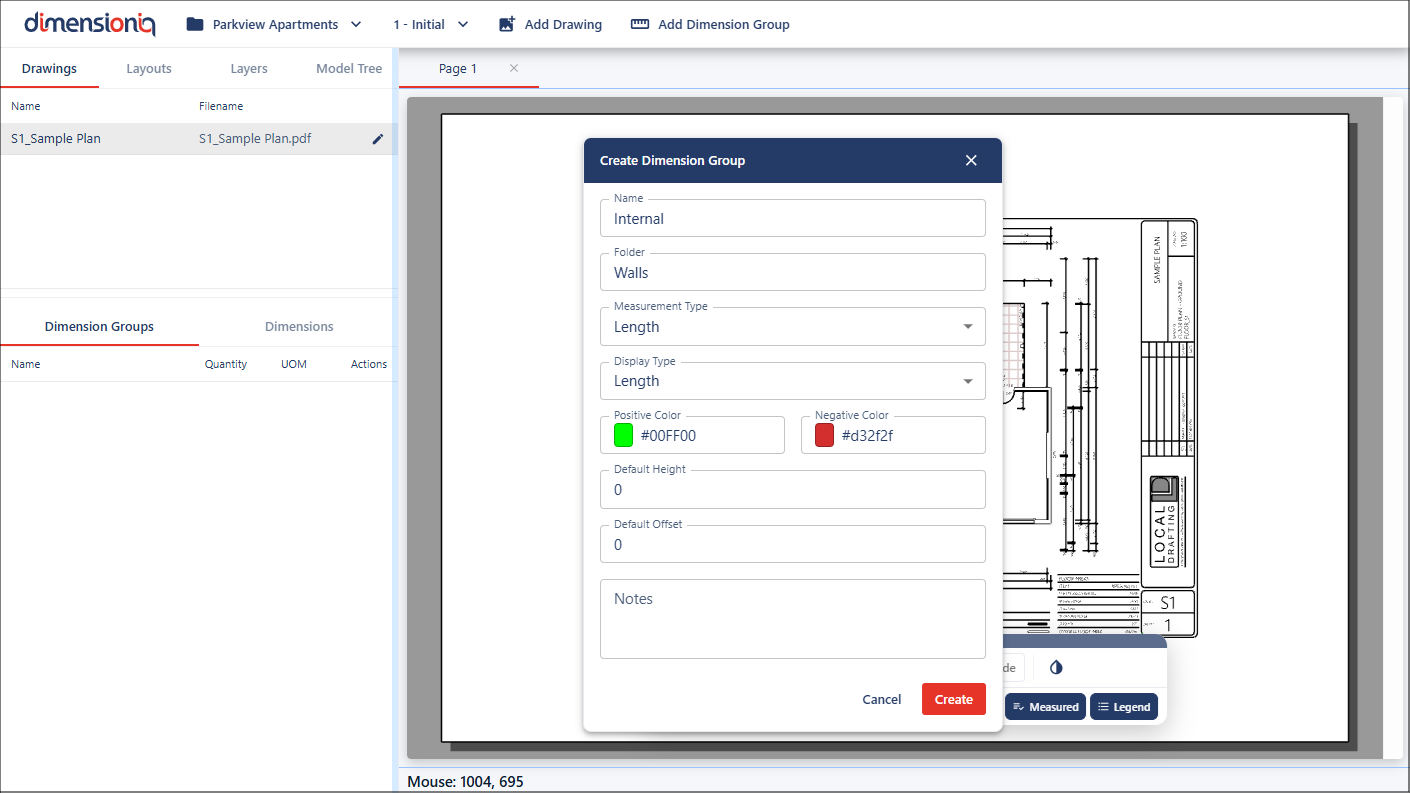
When you click the Create button, your dimension group will be available in its allocated folder in the left-hand-side under the Drawings tab.
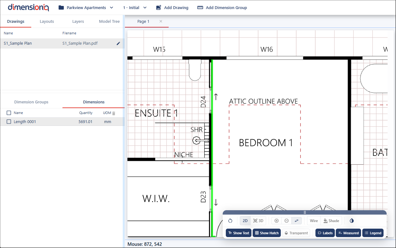
Step 6: Start Measuring
DimensionIQ allows users to take accurate measurements directly from the drawing interface and organize them within selected dimension groups.
Measurements are performed on-screen and are automatically assigned to the currently selected dimension group. The process is designed to be intuitive, simply point and click on the required locations within the drawing to capture dimensions. All dimensions will be available in the Dimensions tab for the selected Dimension Group.
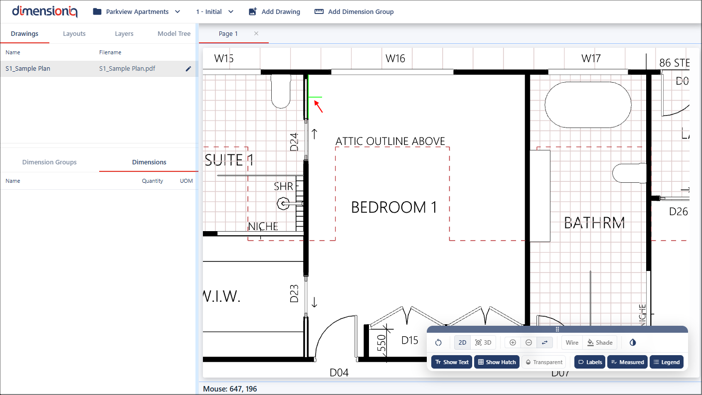
For greater accuracy when taking measurements, it is recommended to zoom in and pan the drawing to clearly position the Snap Cursor on precise points and lines.
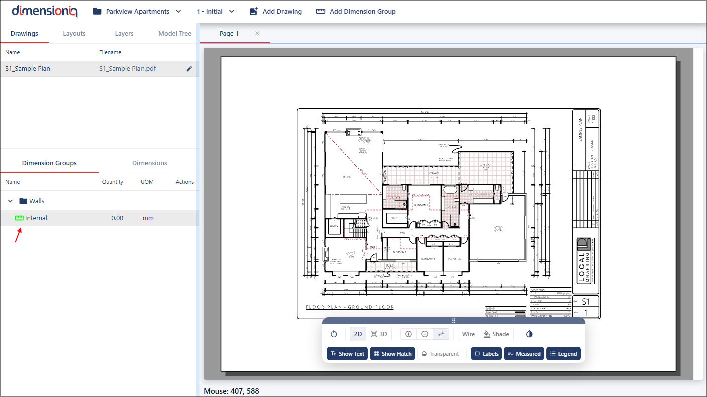
Select your dimension group in the left menu, and click the Dimensions tab.
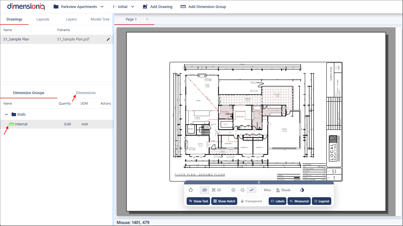
When geometry is present in the drawing, DimensionIQ applies the Snap Cursor. This snap component automatically aligns the cursor to nearby points such as endpoints, intersections, or edges, improving both accuracy and efficiency during measurement. Once you have your measurement selected, click the mouse button to apply the measurement.
As measurements are made, they are visually highlighted on the drawing and listed in the left-hand-side menu grouped by their respective dimension group.
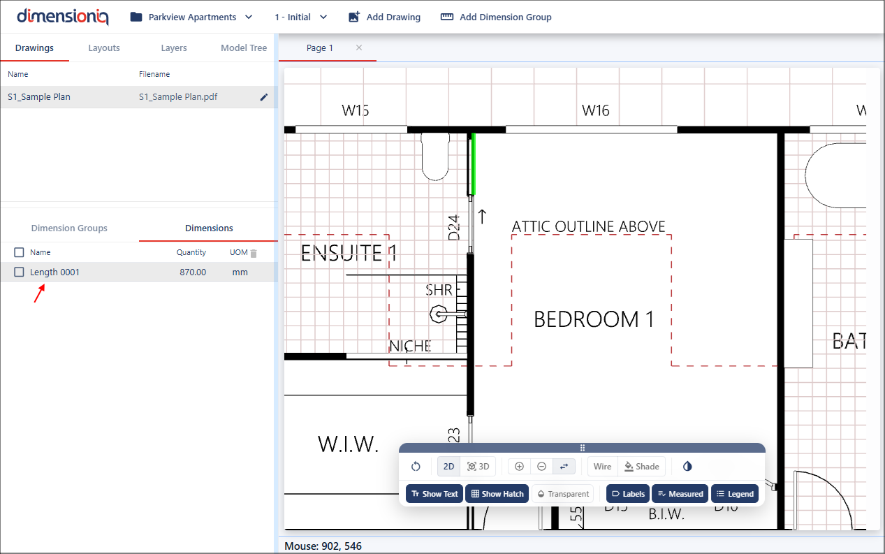
For continuous measurements, hover on the existing dimension in the drawing, hold the Shift key while clicking multiple points. This allows you to continually connect measurements.